
Moulding plugs on power cords needs the machine and the mould set up together, because most faults appear where the two meet: at the pins and at the cord entry. Start with this checklist.
Setup checklist for moulding plugs on power cords
| Setup item | What to set or check | Why it matters |
|---|---|---|
| Pin pockets | Pockets that hold crimped pins at the drawing's spacing and projection | Pin position is checked by gauges in plug testing |
| Cord entry | Shut-off matched to the measured cord diameter range | Stops flash along the jacket and crushed insulation |
| Pre-mould station | A separate cavity for the inner shot, if the design uses one | Locks pins and conductors before the outer shell |
| Gate and vents | Gate into the thick body; vents at last-to-fill points | Avoids burns and short shots near the pins |
| Mould water | Circuits in both halves, held within the compound's range | Sets cooling time and surface finish |
| Mould fit | Inside the tie bars and at least 70% of the gap between them | Stops platen bowing and flash in the centre |
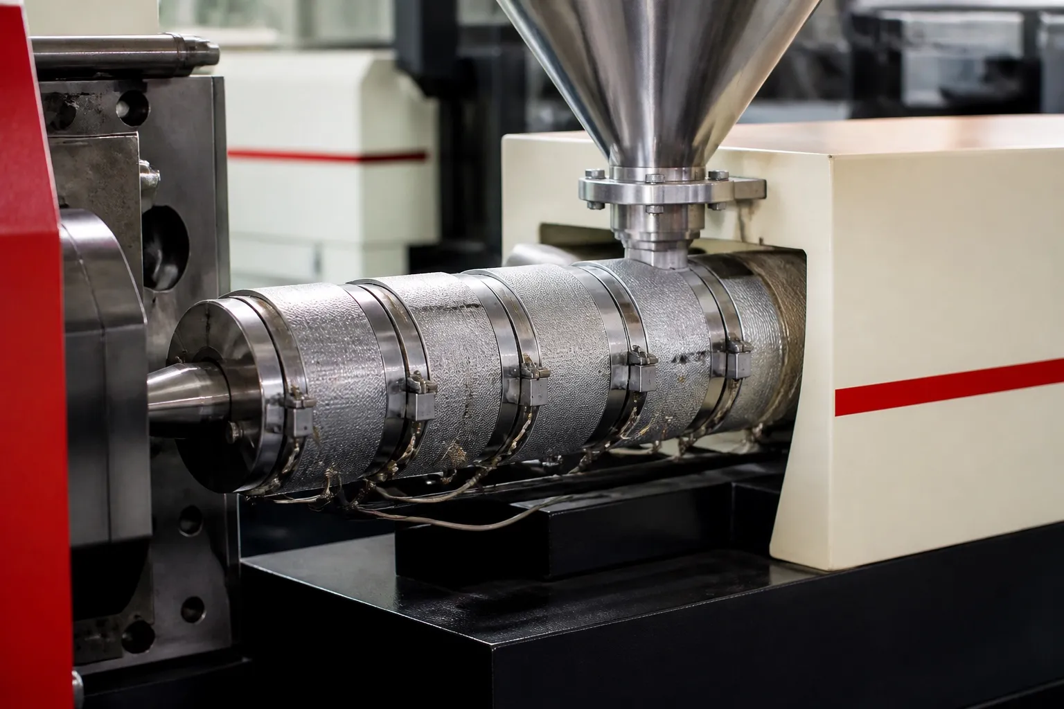
| Clamp and shot | Clamp from projected area; shot within the barrel's PVC window | Covered in the overmoulding and PVC articles in this series |
The sections below explain the items that need the most care, then a worked example sizes the mould and opening for a two-cavity job.
Key Takeaways
- Decide early whether the plug is one shot or a pre-mould plus outer shell, because that sets the number of cavities and stations.
- IS 1293 covers pin dimensions, resistance to abnormal heat and fire, mechanical strength and 10,000 insertion cycles, and each of these has a mould consequence.
- Brass pins are not magnetic, so they must be held by pocket fit or spring detail rather than magnets.
- A mould should cover at least 70% of the tie-bar gap and the opening stroke should be at least 2.5 times the part height.
Is Moulding Plugs on Power Cords Done in One Shot or Two?
Both are used. A one-shot plug forms the body and cord grip in a single fill around crimped pins. A two-shot plug first moulds an inner block that fixes the pins and conductors, then an outer shell that forms the visible body and strain relief tail.
One shot means one cavity set and a simpler cell, but the pins must stay put while the full body fills around them. Two shots add a station and a transfer, but the inner block holds the pins before the larger outer fill arrives, and the two shots can use different compounds.
With two shots, plan the transfer. The operator moves the pre-moulded cord from the first station to the second, so both stations should sit within easy reach and the pre-mould should locate in the second cavity in only one orientation. A pre-mould that can sit the wrong way round will, sooner or later.
Our view: if the cord diameter range and the pin tolerances are not written on the mould drawing, the mould is not ready to cut. Those two numbers decide more scrap than any machine setting.
What Do IS 1293 Tests Mean for the Mould?
IS 1293 covers plugs and socket-outlets in India. Its tests include dimensions, earthing, shock protection, resistance to abnormal heat and fire, mechanical strength by pendulum hammer, and normal operation with the plug inserted and withdrawn 10,000 times. Each test points back to the mould and the process.
Dimensions and insertion cycles depend on pin position. If melt pushes a pin during fill, spacing goes out and the plug may not pass the gauge or may loosen with use. Gate away from the pins, keep injection speed moderate near them and check spacing on first-off parts.
The pendulum hammer test punishes thin walls and weld lines. Keep the wall around the pins even, and avoid a weld line meeting at a pin root.
Pin pockets wear with every cycle as pins are pushed in and parts are pulled out. Make them as replaceable inserts, keep spares, and add the pocket check to the mould maintenance sheet so a worn pocket is found by measurement rather than by a failed plug.
Abnormal heat and fire resistance is a material property first. Mould with the compound approved for the plug, not a substitute.
For plugs on cords, cord grip matters too. The international plug standard IEC 60884-1 includes a cord anchorage test of 100 pulls of 60 N, one per second, followed by a torque test. Check your plug's own standard for its version.
How Do You Fit the Mould to the Machine?
Check four things before the mould arrives: that it fits inside the tie bars, covers enough of the platen, suits the shut height range and gets enough opening to remove the plug with its cord. Then check the gate lines up with the nozzle and water connections reach both halves.
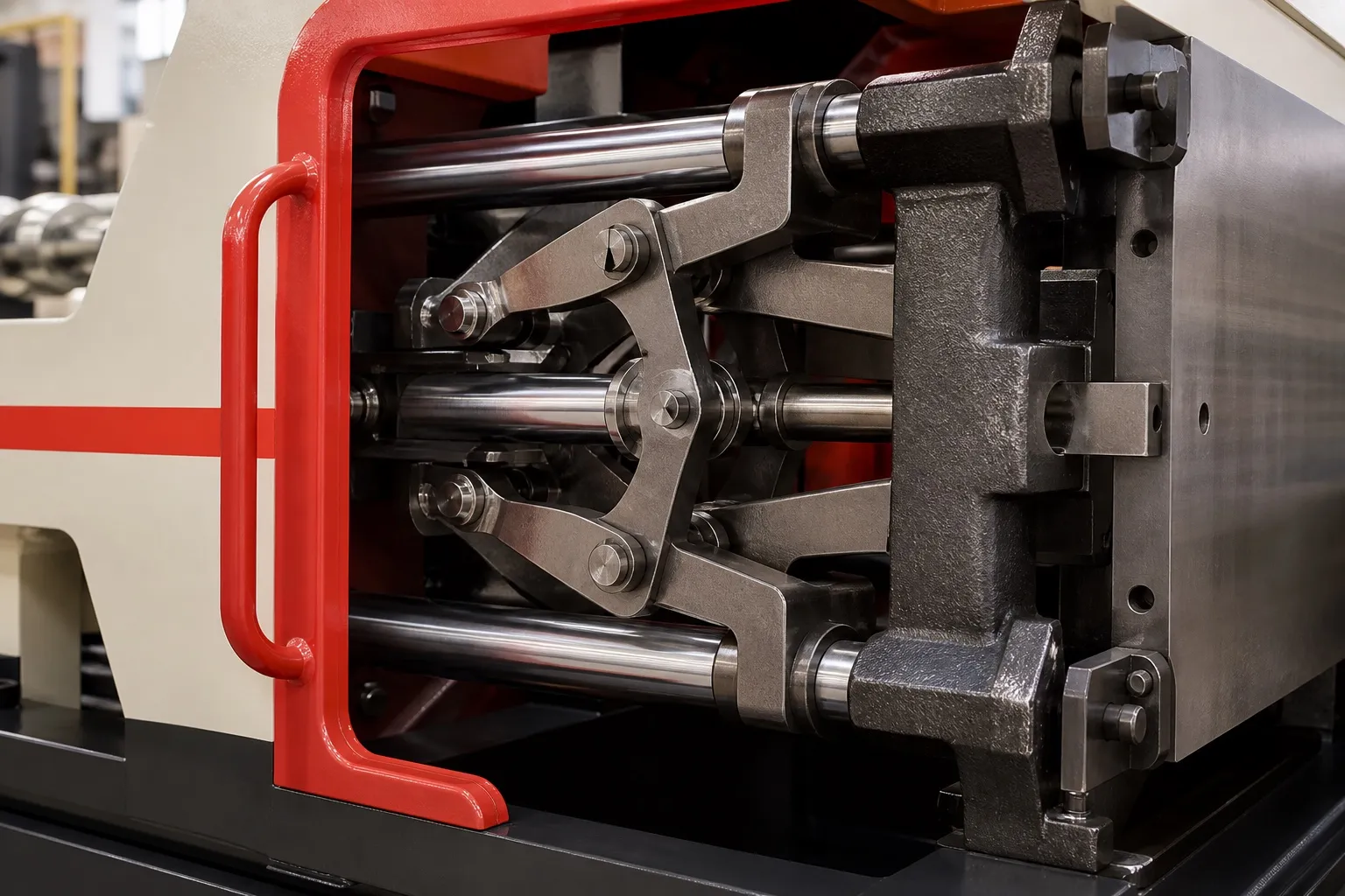
Ideally the whole mould sits inside the tie bars; at minimum, the cavities must. A mould that is too small lets the platens bow under clamp, which can flash the centre of the mould even when tonnage is right.
Ask the toolmaker for the mould height and the opening the part needs, and compare them with the machine's minimum and maximum shut height and its stroke.
On a horizontal clamp with injection from above, the sprue enters at the parting line, so the gate entry in both halves must line up with the nozzle centre. A small offset leaves a step at the sprue that can stick or tear when the mould opens. Check alignment with the mould closed and cold, then again at working temperature.
Run separate water circuits to the cord entry area where possible. The exit zone is where the jacket meets the melt, and being able to cool it on its own helps protect the insulation without slowing the rest of the part.
What Should You Check Before the First Trial?
Bring cords from every supplier, pins from the current batch and the approved compound. Measure cord diameters, confirm pin spacing on the first shots and record the settings that pass. Then share the plug drawing and target output for a machine check. See the horizontal clamp vertical injection moulding machine page.
Frequently Asked Questions About Moulding Plugs on Power Cords
Should the pre-mould and the outer shell use the same compound?
Not necessarily. A harder inner compound can hold pins more firmly, while a flexible outer compound grips the cord and forms a softer strain relief. The two must bond or lock mechanically, so trial the pair together, then confirm with pull and flexing tests on finished plugs before approval.
Why do pins move during injection?
Usually because the pockets are loose, the gate points melt straight at the pins, or injection speed is too high near them. Tighten the pocket fit, move or turn the gate, and slow the first part of fill. Brass is not magnetic, so pins need mechanical location, not magnets.
Can one mould make both two-pin and three-pin plugs?
It can, with interchangeable cavity inserts and pin pockets for each version, but each change means stopping the machine and checking first-off parts again. Where both versions run every day, two dedicated moulds or two cavity sets in one mould can save changeover time and setting errors.
What should the setter record once a plug mould passes?
Record barrel and nozzle settings, the measured melt temperature, injection speed profile, hold pressure and time, mould water temperatures and cycle time. Add the cord supplier and measured diameter, the pin batch and the pin spacing results. These let the next setter repeat a passing plug instead of searching again.
How should pin spacing be checked in production?
Use a gauge built to the plug drawing and standard dimensions, check first-off parts at every start and after any mould maintenance, and then sample at fixed intervals through the shift. Keep failed parts with the time and cavity number, so you can trace a drifting pocket.
Related Articles
- Cable and Wire Overmoulding on Horizontal Clamp Vertical Machines
- Horizontal Clamp or Vertical Clamp? Choosing the Right Vertical Machine
- PVC Moulding for Plugs and Grommets: Temperature and Screw Care
Sources & References
- BIS Blog, N. Agarwal: Standards for Plugs-Socket-Outlets and Switches (Feb 2023)
- Interpower: Cord Anchorage Pull Test
- MoldMaking Technology, B. Catoen: Machine Sizing and Specification for Optimal Mold Performance, Part 1 (Aug 2025)
- Plastics Technology, P. Witaszek, J. Klees, J. Fattori, E. Di Siro, J. Bozzelli: How to Mount an Injection Mold (June 2017)
Technical Disclaimer
Disclaimer: The information provided in this document is for general informational and educational purposes only. It is based on technical references and industry information available at the time of preparation and may be subject to change. It does not constitute engineering, technical, commercial or professional advice, nor does it constitute a quotation, specification, warranty or contractual commitment by Pratishna Engineers.
Actual injection moulding machine and process requirements vary according to the component design, material, mould, production volume, machine configuration and operating conditions. The information, examples, calculations and recommendations provided should be independently evaluated and verified for the specific application before making any equipment, process or production decision. Information obtained from third-party sources remains subject to the accuracy and limitations of those sources.
Limitation of Liability: Pratishna Engineers makes no representation or warranty, express or implied, regarding the completeness, accuracy or suitability of the information for any particular application. To the extent permitted by applicable law, Pratishna Engineers shall not be liable for any loss, damage, cost or consequence arising from reliance on or use of the information contained in this document. Final machine selection, configuration and application suitability should be confirmed with Pratishna Engineers based on complete and accurate project requirements.