






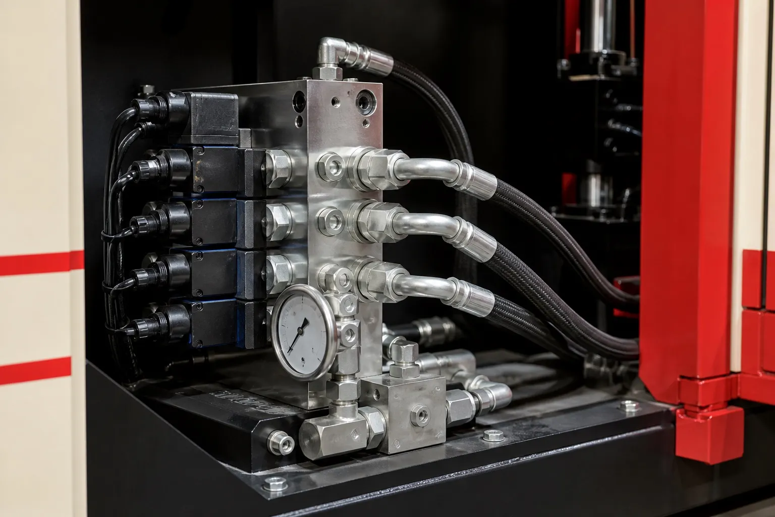

An operator picks up a cord with brass pins already crimped on, seats the pins in their pockets, lays the cord in its groove and closes the guard. Seconds later a finished plug comes out, bonded to the jacket. That is the whole job of a power cord plug moulding machine: hold the pins true, close on the cord without crushing it, fill the body and repeat at the operator's pace.
On a 40 t machine with a horizontal clamp and injection from above, the clamp is seldom the limit for plugs, as the applications article in this series shows. Pin location and the bond to the jacket decide quality. The operator's hands decide output.
Key Takeaways
- A moulded plug can be made in two shots: an inner pre-mould that fixes the pins, then an outer body with its strain relief.
- IS 1293 covers earthing, shock protection, dimensions, abnormal heat and fire, pendulum hammer strength and 10,000 insertions.
- Voids, short shots near the pins and pin movement are the moulding faults those tests expose.
- Plan output from loading time per cord; a second cavity adds output, but it also adds loading work.
What Does a Power Cord Plug Moulding Machine Have to Do?
It has four jobs every cycle: hold the crimped pins at the right spacing, close on the cord jacket without crushing it, fill the plug body without voids, and open quickly for the operator. Repeatable mould closing and steady injection matter more here than clamp force.
The pins are the critical insert. If they shift while the melt flows in, their spacing falls outside the gauge and the plug will not fit the socket. Pockets in the mould, or an inner pre-mould, hold them in place. Keep melt pressure at the pins as low as the fill allows.
The cord is the second insert. The mould closes on its jacket where it leaves the cavity. Too loose a fit lets melt run along the cable as flash; too tight a fit crushes the jacket and can damage the conductors inside.
Injection from above at the parting line suits this work. The cord lies across the parting face with nothing in its way, and the gate can sit on the body where a small mark will not show.
Why Mould the Plug in Two Shots?
Because one shot struggles to hold the pins and fill a thick body at the same time. A small inner pre-mould locks the pins at their spacing and insulates the terminations. The outer shot then forms the body and strain relief around a core that can no longer move.
The pre-mould can be a stiffer material than the outer body, chosen to hold dimensions. Where the cord is PVC, the outer body is a flexible PVC that bonds to the jacket and gives the grip and the strain relief tail. Each shot runs in its own mould, on one machine or two.
Moulding metal in has known risks. A PlasticsToday summary of DuPont insert moulding guidance lists inserts that float or damage the mould, flash, slow loading and costly rejects. It recommends rounded inserts with no sharp corners, and preheating inserts for better weld lines and less post-mould shrinkage.
The same guidance flags delayed cracking from hoop stress around metal inserts in rigid plastics, estimated as mould shrinkage times flexural modulus. A soft PVC outer body has a low modulus and is less exposed, but a rigid pre-mould around brass pins is not.
What Does IS 1293 Ask of a Moulded Plug?
IS 1293 covers plugs and socket-outlets. A BIS article on the standard lists tests for earthing, protection against shock, dimensions, resistance to abnormal heat and fire, mechanical strength with a pendulum hammer, and normal operation, where a plug is inserted and withdrawn 10,000 times. Each test has a moulding consequence.
IS 1293 test areas and what they ask of the moulding process
| IS 1293 test area | What can fail in a moulded plug | What to control at the machine |
|---|---|---|
| Dimensions | Pin spacing or body size out of gauge | Pin pockets or pre-mould, low pressure near the pins, steady shrinkage |
| Protection against shock | Thin or missing insulation over the terminations | Full fill of the pre-mould; no short shots at thin sections |
| Earthing | Earth pin loose or misplaced | Correct pin seating checked before every cycle |
| Resistance to abnormal heat and fire | Compound not suited to the test | Grade approved before tooling; no unapproved regrind |
| Mechanical strength (pendulum hammer) | Cracks starting at voids, weld lines or brittle compound | Pack the body fully; avoid overheated compound |
| Normal operation (10,000 insertions) | Pins loosening in the body over repeated use | Good bond around the pins; no voids behind them |
The BIS article notes that these accessories are made from both thermoset and thermoplastic materials. For plugs moulded onto cords the compound is a thermoplastic, and its grade has to be approved for the plug before production starts, not swapped later for a cheaper one.
Our view: run the pendulum hammer and insertion checks on the first trial plugs, not after the mould is approved. Voids behind the pins show up there first, and they are cheaper to fix in steel than in production.
How Fast Can a Manual Plug Cell Run?
In a hand-loaded cell, output is set by how fast the operator can load cords safely. Fill and mould movement take a few seconds; seating pins, laying cords and removing finished plugs take much longer. Time the loading on a real cord before you set an output target.
A Robotic Industries Association case study shows the scale. Unloading a four-cavity insert mould, inspecting the cavities for debris, and loading and verifying inserts took 30 seconds. A SCARA robot, a vibratory bowl feeder and vision checks were added to take over that work.
Output per hour is 3,600 divided by the cycle in seconds, times cavities, times the share of good shots. A second cavity raises output, but the cycle grows too, because two cords take longer to load than one. The worked example below shows the effect.
Automation is worth a look when volumes are steady and cord length is fixed. For short runs of many cord lengths and plug types, a well-laid-out manual cell with good fixtures can be easier to keep running.
What Should You Prepare Before Trials?
Prepare crimped cords from production, the plug drawing with pin gauge dimensions, the compound grade and your target per shift. Time one loading cycle with a real operator, then size cavities from that time, not from the dry cycle. See the 40 ton vertical injection moulding machine page.
Frequently Asked Questions About Power Cord Plug Moulding
Why do some plugs crack near the pins weeks after moulding?
Delayed cracking around metal inserts comes from hoop stress as the plastic shrinks onto the insert. It is worst in stiff materials with high shrinkage. Rounded pins with no sharp edges, preheated inserts and a tougher grade for the pre-mould all reduce the risk. Test with temperature cycling, not only at room temperature.
Can rejected plugs be ground and reused?
Only after the brass pins and copper are removed, and only within the regrind share the compound supplier and your approved plug specification allow. Metal fragments in regrind can damage the screw and cause electrical faults in the next plug. Scrapping plug rejects can cost less than separating the metal from them.
What causes flash along the cord?
Flash along the jacket means melt is escaping at the cable exit. The usual causes are a cord thinner than the shut-off, a worn exit, or injection and hold pressure set higher than the part needs. Measure cords from several reels and check that the shut-off matches the thinnest you will receive.
Should brass pins be preheated before moulding?
Preheating inserts is recommended in insert moulding guidance because it reduces post-mould shrinkage onto the insert and improves weld lines. Brass conducts heat away from the melt quickly, so cold pins can freeze the melt early. Trial with and without preheating, and compare pull-out and insertion results.
Is a vertical injection machine needed for every plug?
No. A rewireable plug top, moulded as a separate body with loose brass pins, is an insert job suited to a vertical clamp with an upward-facing lower mould. A plug moulded permanently onto a cord suits a horizontal clamp with injection from above, because the cord lies across the parting line.
Related Articles
- What Can You Make on a 40 Ton Vertical Moulding Machine?
- Cable Grommets and Strain Reliefs: Mould and Machine Setup
- 40 Ton vs 55 Ton Vertical Machine: Which Suits Your Cable Part?
Sources & References
- BIS Blog, N. Agarwal: Standards for Plugs-Socket-Outlets and Switches
- PlasticsToday, summarising A. Miller (DuPont): Design and material advice from the pros, Part 3: Insert molding essentials
- Robotic Industries Association via Smart Molding, J. Clark: Automated injection molding operation
Technical Disclaimer
Disclaimer: The information provided in this document is for general informational and educational purposes only. It is based on technical references and industry information available at the time of preparation and may be subject to change. It does not constitute engineering, technical, commercial or professional advice, nor does it constitute a quotation, specification, warranty or contractual commitment by Pratishna Engineers.
Actual injection moulding machine and process requirements vary according to the component design, material, mould, production volume, machine configuration and operating conditions. The information, examples, calculations and recommendations provided should be independently evaluated and verified for the specific application before making any equipment, process or production decision. Information obtained from third-party sources remains subject to the accuracy and limitations of those sources.
Limitation of Liability: Pratishna Engineers makes no representation or warranty, express or implied, regarding the completeness, accuracy or suitability of the information for any particular application. To the extent permitted by applicable law, Pratishna Engineers shall not be liable for any loss, damage, cost or consequence arising from reliance on or use of the information contained in this document. Final machine selection, configuration and application suitability should be confirmed with Pratishna Engineers based on complete and accurate project requirements.

