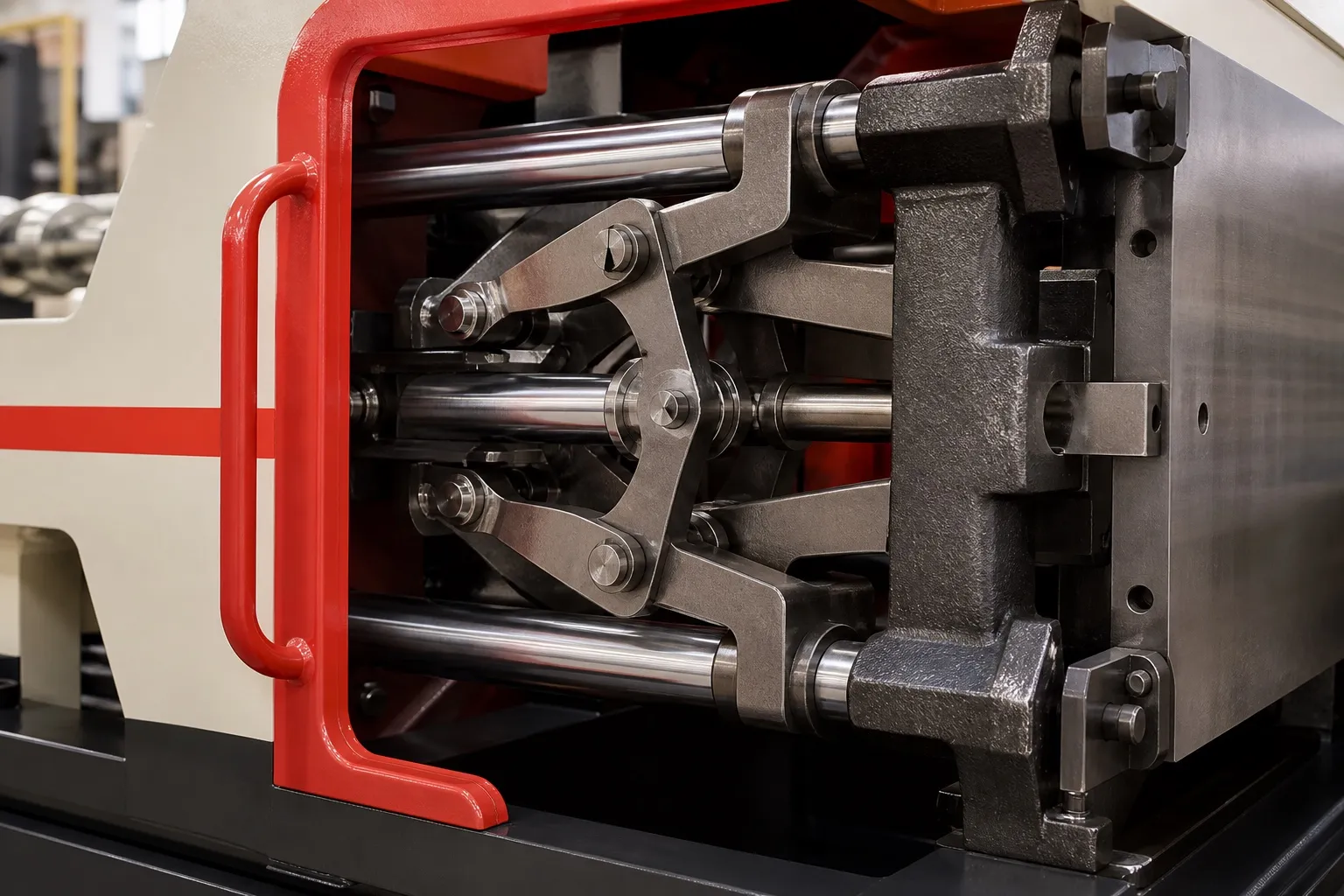
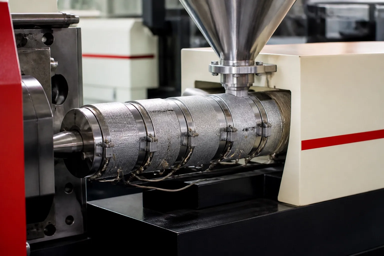
Wire overmoulding on a vertical machine with a horizontal clamp works like this. The operator lays the cable across the parting line, the two mould halves close sideways around it, and the injection unit fills the cavity from above. Shaped grooves on either side of the cavity grip the cable, and the melt forms a boot, grommet, clip or plug body straight onto the jacket.
Three things decide whether the part is good: how well the grooves seal on the cable without crushing it, whether the moulding material suits the jacket, and whether the mould is sized for the machine rather than for the clamp force alone.
Key Takeaways
- A horizontal clamp with injection from above leaves both sides of the parting line free, so the cable can run straight through the mould.
- The cable groove is the seal: too tight and it cuts the jacket, too loose and melt flashes along it.
- Choose an overmould material that suits the jacket; PVC on a PVC jacket is a natural pairing, and the jacket itself is a certified product.
- Clamp force can be small on cable parts; mould width, cable pitch and handling may set the cavity count first.
Why do cable jobs suit a horizontal clamp with vertical injection?
The cable has to pass through the mould and leave on both sides. With a horizontal clamp the parting line is vertical, the cable lies across it in grooves, and the injection unit fills from above at the parting line, so nothing blocks the cable path.
The operator lays each cable into its groove, closes the guard, and the mould shuts around it. Long leads hang clear below or beside the mould instead of piling on a platen. A vertical clamp, by contrast, suits pins and bushes dropped into an upward-facing lower half. The clamp comparison article in this series weighs the two in full.
Because the nozzle meets the mould at the parting line, the sprue and runner sit in the split between the halves and come out with the parts each cycle. Place the gate so the melt front reaches the jacket from the side or along it, not head-on, and the cable is less likely to shift or scorch.
How does the mould seal on the cable?
Each side of the cavity has a groove sized to the cable outside diameter, so the closing mould grips the jacket and stops melt escaping. The fit must allow for the cable's own tolerance: too tight cuts or flattens the jacket, too loose lets plastic flash along it.
Measure the cable before you cut the grooves, and again on every new drum. Cable diameter can drift between suppliers and batches, and a groove sized for the thickest cable will flash on the thinnest. Where the spread is wide, replaceable groove inserts let you change the seal without reworking the whole mould.
Our flat view: never try to stop flash by raising clamp force on a cable mould. The extra force goes straight into the jacket and the conductors. The cable is a certified product in its own right; PVC cables to IS 694 sit under compulsory BIS certification through the Electrical Wires, Cables, Appliances and Protection Devices and Accessories (Quality Control) Order, 2003, and a crushed jacket undoes that before your part is even finished.
Cable seal features in a wire overmoulding mould
| Feature | Purpose | Watch for |
|---|---|---|
| Groove on each side of the cavity | Grips and seals the jacket | Flash if loose, cut jacket if tight |
| Replaceable groove insert | Matches different cable sizes | Wear at the sealing edge |
| Cable clamp outside the mould | Holds position during injection | Cable pulled into the cavity |
| Stop or locator for the cable end | Sets overmould position on the lead | Inconsistent length to the boot |
Which materials bond to a cable jacket?
The overmould should suit the jacket chemically and thermally. PVC moulded onto a PVC jacket is a natural pairing, because the hot melt softens the jacket surface and the two fuse. Other jackets and parts call for thermoplastic elastomers, chosen for adhesion, flexibility and the service temperature.
Automotive cable ducts show the trade-offs. A Teknor Apex selector guide notes that EPDM rubber is dense, slow to cycle and cannot be recycled, that TPVs can be hard to demould on complex shapes, and that standard styrenic TPEs have a narrow processing window. It also lists the material demands carmakers set, from low odour and fogging to flame resistance and a wide operating temperature range.
PVC processing needs its own care, from melt temperature to screw metal. The PVC moulding article in this series covers it in full.
How many cavities can a wire overmoulding mould carry?
Check the clamp, but expect other limits to bite first, because small cable parts have little projected area. Those limits are the cable pitch, the mould width that fits between the tie bars, and how quickly the operator can lay and remove every cable in a cycle.
Mould size cuts both ways. A Plastics Technology guide gives a rule of thumb that a mould should cover at least 70% of the distance between the tie bars; smaller moulds let the platens bow under clamp and flash in the middle of the mould. A narrow cable mould on a wide machine is a flash risk, not a safety margin.
What should you send to plan a wire overmoulding job?
Send the part drawing, the cable type and outside diameter with its tolerance, the jacket material, the moulding material, the lead length on each side and the cavity count you want. See the horizontal clamp vertical injection machines page for the machines such a job is matched to.
Frequently Asked Questions About Wire Overmoulding
Can wire overmoulding be done on a horizontal injection machine?
It can, but the cable has to be fed into a mould face that stands upright, and leads may hang across tie bars or the platen. A horizontal clamp with injection from above at the parting line gives the cable a clear path through the mould and lets the operator lay it in by hand.
Why does the cable jacket melt or wrinkle under the overmould?
The melt is hotter than the jacket can take for that long, the gate points straight at the jacket, or the jacket is a material that softens easily. Lower the melt temperature within the resin's window, move or enlarge the gate so the flow is gentler, and check the jacket material.
How tight should the cable groove be?
Tight enough to seal against the smallest cable you will receive, but not so tight that it cuts the largest. Measure a sample of cables from several drums, size the groove to that spread, and use replaceable groove inserts if the spread is too wide for one fixed size.
Does a cable need preparation before overmoulding?
Yes. The jacket should be clean and dry, the cut end and any stripped length must be correct, and terminals or crimps must already be fitted. Oil, dust or moisture on the jacket can weaken the bond, and a stripped length that varies will move the overmould along the cable.
Can one machine run several cable diameters?
Yes, with one mould per cable size or replaceable groove inserts in a common mould. What changes between sizes is the groove fit, not the clamp or injection unit. Keep a record of which insert set matches which cable, so setters do not mount the wrong grooves for a new drum.
Related Articles
- Moulding Plugs on Power Cords: Machine and Mould Setup
- Horizontal Clamp or Vertical Clamp? Choosing Between PV and PVDL
- PVC Moulding for Plugs and Grommets: Temperature and Screw Care
Sources & References
- BIS: Scheme I (ISI Mark Scheme): products under compulsory certification
- Teknor Apex: Sarlink TPE for Cable Ducts: Product Selector Guide (Aug 2024)
- Plastics Technology, P. Witaszek, J. Klees, J. Fattori, E. Di Siro, J. Bozzelli: How to Mount an Injection Mold (June 2017)
- GEON Performance Solutions: Injection Molding Guide: GEON PVC Molding Formulations (PG0019BC, 2021)
Technical Disclaimer
Disclaimer: The information provided in this document is for general informational and educational purposes only. It is based on technical references and industry information available at the time of preparation and may be subject to change. It does not constitute engineering, technical, commercial or professional advice, nor does it constitute a quotation, specification, warranty or contractual commitment by Pratishna Engineers.
Actual injection moulding machine and process requirements vary according to the component design, material, mould, production volume, machine configuration and operating conditions. The information, examples, calculations and recommendations provided should be independently evaluated and verified for the specific application before making any equipment, process or production decision. Information obtained from third-party sources remains subject to the accuracy and limitations of those sources.
Limitation of Liability: Pratishna Engineers makes no representation or warranty, express or implied, regarding the completeness, accuracy or suitability of the information for any particular application. To the extent permitted by applicable law, Pratishna Engineers shall not be liable for any loss, damage, cost or consequence arising from reliance on or use of the information contained in this document. Final machine selection, configuration and application suitability should be confirmed with Pratishna Engineers based on complete and accurate project requirements.