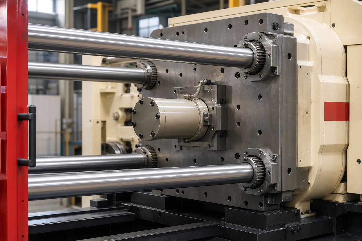
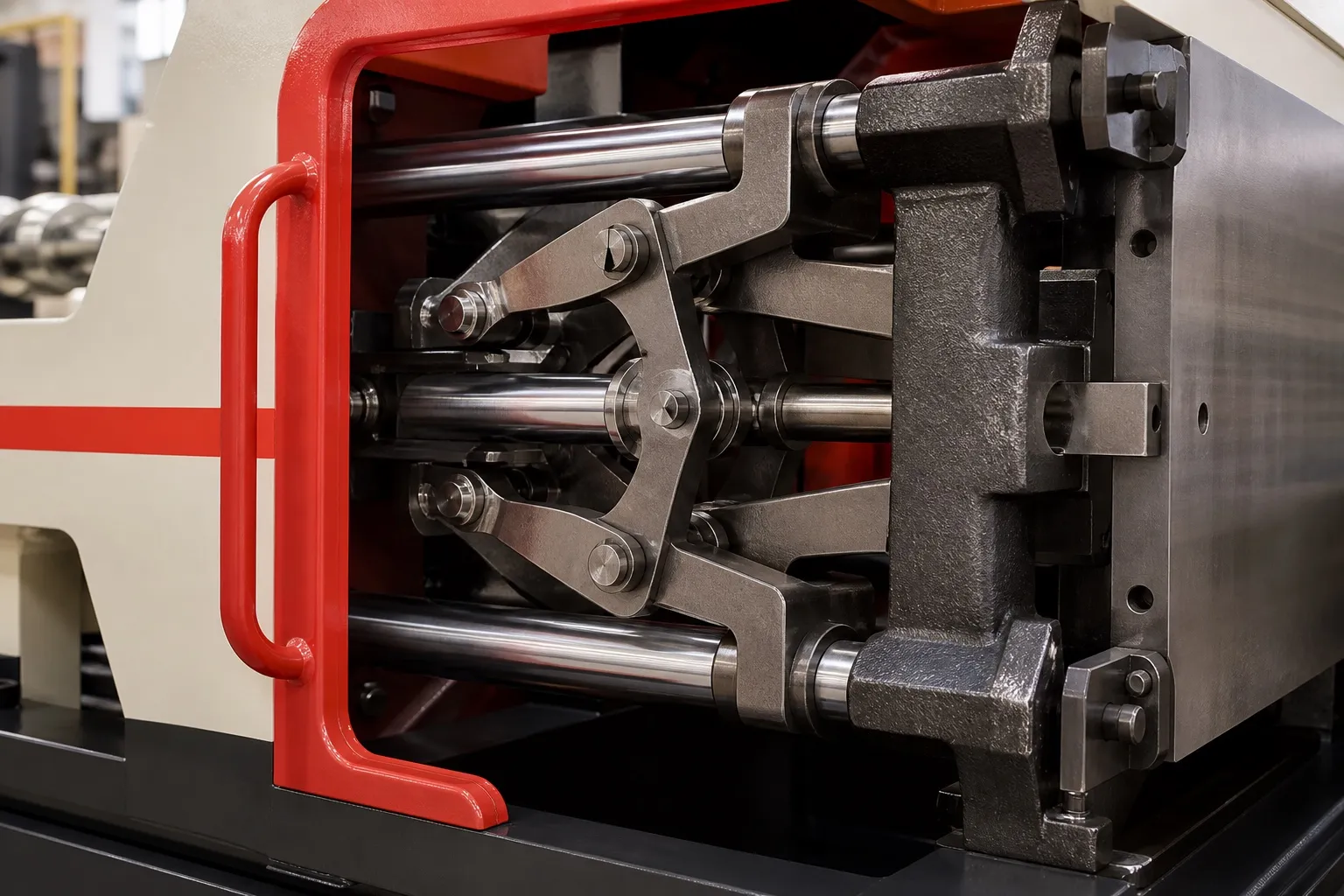
Hydro-mechanical clamping locks the moving platen to the tie bars mechanically, then builds clamp force hydraulically with short-stroke cylinders. Small, fast cylinders move the platen, split nuts or similar locks grip the tie bars, and pressure in the clamp cylinders stretches the tie bars to hold the mould shut. Because the force comes from oil pressure, you can set it close to what the part needs. And because the clamp cylinders share one oil pressure, each tie bar is pulled with similar force. Those two features are why it helps large, flat parts come out without flash.
Key Takeaways
- Hydro-mechanical clamping splits the work: fast travel, a mechanical lock on the tie bars, then a short high-pressure stroke for tonnage.
- Clamp force is a pressure setting, so you can run at what the part needs instead of the machine maximum.
- Flash on large, flat parts can come from platen bowing, mould fit, vents or the process, not only from a tonnage shortage.
- Over-clamping is not a safe fix. It crushes vents, can crack mould blocks and hides the real cause of the flash.
How does hydro-mechanical clamping work, step by step?
It works in four steps. Fast, small cylinders close the moving platen. Locks on the moving platen grip the tie bars. Short-stroke clamp cylinders build tonnage by stretching the tie bars. On opening, the cylinders release pressure, the locks open and the fast cylinders pull the platen back.
Plastics Technology describes the same principle: split nuts or similar devices lock the moving platen, then one or more short-stroke "pancake" cylinders apply the tonnage. The long travel and the high force are handled by different parts, so neither has to do both jobs. A fully hydraulic clamp, by contrast, uses one long ram for travel and force, which means a large oil volume moving on every cycle.
Hydro-mechanical clamping sequence and what to watch at each step
| Step | What moves | What to watch |
|---|---|---|
| 1. Mould close | Fast cylinders, low force | Mould protection pressure and the slow-down point before the faces meet |
| 2. Lock | Split nuts close on the tie-bar grooves | Full nut engagement before any tonnage builds |
| 3. Clamp build-up | Clamp cylinders over a short stroke | Set tonnage reached and held steady |
| 4. Injection and hold | Pressure held while the cavity fills and packs | Tonnage reading shot to shot |
| 5. Break and open | Clamp cylinders reverse, nuts release, fast cylinders retract | Enough breaking force for deep cores |
Why does balanced clamp force reduce flash on large parts?
Flash forms where melt pressure pushes the mould halves apart at the parting line. If clamp force reaches the mould evenly and the platens stay flat, the parting line stays shut everywhere. If one side or the centre opens slightly, melt escapes there first, even when total tonnage looks ample.
Plastics Technology reports that toggles, since most apply force at the platen corners, carry a potential for higher platen deflection, and that direct hydraulic clamping is reported to give more uniform pressure. The full clamp-type comparison is in the two platen vs toggle article in this series.
Mould size matters as much as clamp type. A rule of thumb in the same magazine's mould-mounting guidance is that the mould should cover at least 70% of the distance between the tie bars. Smaller moulds let the platens bow under clamp, which shows up as flash in the centre of the mould, and very small moulds can cause serious platen damage.
Flash can also have nothing to do with the clamp. Low melt viscosity, too fast an injection, a pressure peak at transfer or too much early hold pressure can all push melt past a tight parting line. Shallow vents trap gas, and repeated clamping can coin vents shut. Recycled resin adds a further variable here. Under the PWM (Amendment) Rules notified on 31 March 2026, rigid plastic packaging must contain at least 30% recycled material in 2025-26, rising to 60% by 2028-29. Recycled PP can vary from lot to lot, so a parting line that stayed shut on virgin resin may flash on a lower-viscosity recycled lot.
How much clamp force should you set to avoid flash?
Set clamp force from the part, not from the machine maximum. Multiply projected area by a tonnage factor for the resin, add a starting margin, then raise it only if flash appears and other causes are ruled out. Over-clamping crushes vents and can crack mould blocks.
Plastics Technology recommends 3 US tons per square inch as a starting factor, within a typical range of 2 to 10, applied to the projected area of every cavity plus the full cold-runner area. In metric terms, 3 tons/in² is about 0.422 t/cm². Add 10% on top as a starting margin, not a rule. The same article describes a mould that needed about 100 tons being clamped at a 400-ton machine's maximum; the cavity block split in two places, at a cost above $100,000.
This is where hydro-mechanical clamping earns its keep. Because tonnage is a pressure setting, running a 350 t machine at about 200 t for a particular mould is routine. On a toggle, Plastics Technology reports, running below maximum can be harder, and die height set on a cold mould can over-clamp once the mould warms.
Do not cure flash by adding tonnage until you have checked vents, mould support and transfer pressure. Extra tonnage hides the cause, and the mould pays for it.
What should you do next about flash on large parts?
Start with numbers. Work out the projected area and the clamp force the part needs, measure the mould against the tie-bar gap, and record where the flash appears: centre, corners or one side. Centre flash points to platen support or mould size, flash on one side to parallelism or mould fit, and flash only on some resin lots to the material. Take that record to your machine supplier. For large parts that need a long opening as well as even clamping, see the two platen injection moulding machine range.
Frequently Asked Questions About Hydro-Mechanical Clamping
Is hydro-mechanical clamping the same as fully hydraulic clamping?
No. A fully hydraulic clamp moves and clamps with one large cylinder behind the moving platen, so it needs a long, large-bore ram and a lot of oil. Hydro-mechanical clamping splits the job: small fast cylinders move the platen, mechanical locks hold the tie bars and short cylinders build the tonnage.
What are split nuts on a two platen machine?
Split nuts are half-nut locks on the moving platen that close around grooves on the tie bars. Once they close, the platen is tied mechanically to the tie bars and the short clamp cylinders can apply tonnage. If the nuts do not fully engage, the machine should not build clamp pressure.
Can I lower clamp force on an existing mould?
Often, yes. Reduce tonnage in steps, check part weight and the parting line after each step, and stop at the point where flash appears, then go back up a step and add your margin. Running at the force the part needs reduces load on the mould, vents and platens.
Why does flash appear only in the centre of my mould?
Centre flash on a big platen often means the platens are bowing because the mould is too small for the tie-bar spacing. A rule of thumb from Plastics Technology is that the mould should cover at least 70% of the tie-bar distance. Support pillars, plate thickness and vents near the centre are also worth checking.
Does clamp force affect part quality?
Yes. Too little clamp lets the parting line open and adds flash and weight. Too much can crush vents, causing burns and short shots, and can roll the parting line. Plastics Technology also lists gloss changes, broken inserts and cracked blocks as over-clamping effects. Set tonnage once, then confirm it with part weights.
Related Articles
- Two Platen vs Toggle Injection Moulding Machines: Which Suits Large Moulds?
- Moulding Buckets, Crates and Dustbins on Two Platen Machines
- Deep Moulds and Long Opening Strokes: Planning Mould Height and Daylight
Sources & References
- Plastics Technology, M. Knights: Hybrid Injection Clamps: The Best of Both Worlds? (June 2010)
- Plastics Technology, J. Williams (RJG): Clamp Tonnage: More Is Better...Right? (May 2017)
- Plastics Technology, P. Witaszek, J. Klees, J. Fattori, E. Di Siro, J. Bozzelli: How to Mount an Injection Mold (June 2017)
- Polymerupdate, D. K. Jha: India eases plastic recycling regulations (8 Apr 2026)
Technical Disclaimer
Disclaimer: The information provided in this document is for general informational and educational purposes only. It is based on technical references and industry information available at the time of preparation and may be subject to change. It does not constitute engineering, technical, commercial or professional advice, nor does it constitute a quotation, specification, warranty or contractual commitment by Pratishna Engineers.
Actual injection moulding machine and process requirements vary according to the component design, material, mould, production volume, machine configuration and operating conditions. The information, examples, calculations and recommendations provided should be independently evaluated and verified for the specific application before making any equipment, process or production decision. Information obtained from third-party sources remains subject to the accuracy and limitations of those sources.
Limitation of Liability: Pratishna Engineers makes no representation or warranty, express or implied, regarding the completeness, accuracy or suitability of the information for any particular application. To the extent permitted by applicable law, Pratishna Engineers shall not be liable for any loss, damage, cost or consequence arising from reliance on or use of the information contained in this document. Final machine selection, configuration and application suitability should be confirmed with Pratishna Engineers based on complete and accurate project requirements.