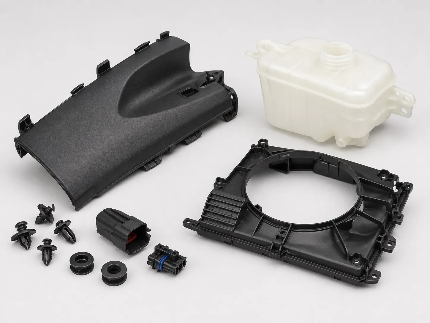

Ten inserts per shot. That is what a two-cavity housing with four brass threaded inserts and one earth stud in each cavity asks of the operator before every cycle. At an assumed 2 s per insert, the mould stands open for 20 s for loading alone. In multi insert moulding, that open time can set the output before the clamp does.
An 80 t vertical machine suits these housings because the lower mould faces up and each insert stays where it is placed. This article covers which inserts to mould in, how to design and locate them, how long loading takes, and what the Indian enclosure standard asks of the inserts.
Key Takeaways
- Each insert adds placement time: ten inserts at an assumed 2 s each add 20 s of open mould per shot.
- Long-standing design guidance gives a boss about 1.5 times the insert diameter and at least one sixth of the diameter of plastic beneath it.
- Diamond knurls resist load in all directions; straight knurls give the most torque resistance but less pull-out.
- IS 14772 asks enclosures for earthing provision and protected screw fixings, which is where earth terminals and fixing inserts come from.
What Makes Multi Insert Moulding Different From Single-Insert Work?
Every insert is another placement, another pocket that can be missed and another boss that can crack. Loading time grows with the insert count, and so does risk: one unseated insert can float, damage the mould or let flash into a thread. Plan the design and the loading together.
Start by asking which inserts must be moulded in at all. A DuPont design guide summarised in PlasticsToday gives three reasons: serviceable threads under stress or frequent disassembly, close-tolerance female threads, and a permanent joint between high-load parts. Inserts can often be pressed, snap-fitted or ultrasonically inserted into a moulded part instead, and the guide calls moulding in a last resort for that reason.
The same guide lists the costs: inserts that float or damage the mould, flash in internal threads, slow loading, preheating, and rejects that are expensive to salvage. Heat staking is the other route; a PennEngineering article in Plastics Technology calls it the more common method for thermoplastics, because it is easy to control and suits automation. It works only on thermoplastics.
How Should the Inserts Be Designed and Located?
Use rounded inserts or knurls, a boss about 1.5 times the insert diameter, at least one sixth of the diameter of plastic beneath, and at least 0.4 mm of protrusion into the cavity. Then locate each insert on a pin or in a pocket that fixes its height.
Insert design and location guidance for multi-insert housings
| Item | Guidance | Source |
|---|---|---|
| Boss outer diameter | About 1.5 × insert diameter, for inserts up to 12.9 mm | DuPont via PlasticsToday |
| Plastic beneath the insert | At least 1/6 of the insert diameter | DuPont via PlasticsToday |
| Protrusion into the cavity | At least 0.4 mm | DuPont via PlasticsToday |
| Corners and knurls | Rounded, no sharp corners; an undercut resists pull-out | DuPont via PlasticsToday |
| Knurl pattern | Diamond resists all directions; straight gives most torque, less pull-out; grooves between bands raise pull-out | PennEngineering via Plastics Technology |
| Through vs blind threads | Through-threaded: solid contact with core and cavity to keep resin out; blind: no cavity contact needed | PennEngineering via Plastics Technology |
Moulded-in inserts sit over pins in the mould each cycle, and the fit between pin and insert needs close tolerance. Measure insert bores from more than one supplier lot before the pins are finished, because a loose fit lets resin into the thread and a tight one stops the insert seating.
Cracking around bosses from hoop stress is worked through in the automotive article in this series.
How Much Time Does Loading Add?
Roughly the number of inserts multiplied by the time to place one, plus part removal and a cavity check. On a fixed lower mould all of that happens with the clamp open, so it adds directly to the cycle. Time the routine on a trial fixture before quoting an output.
Our view: standardise insert sizes across a housing wherever the design allows. Every extra size is another chance to put the wrong insert in the wrong pocket, and a mixed tray slows the hand. Where two sizes cannot be avoided, give their pins different diameters so a wrong insert will not sit down.
How inserts reach the operator matters as much as how many there are. Inserts tipped loose into a tray must be picked and turned the right way up; inserts presented in an oriented nest can be picked in one move. A fixture that holds a full shot of inserts in the mould layout lets the operator, or later a gripper, place them together.
When loading time gets close to the time the mould is closed, a second lower half on a sliding or rotary table lets loading overlap moulding. The sliding mould article in this series works through that choice.
What Does IS 14772 Ask of an Enclosure?
IS 14772:2020 covers boxes and enclosures for household and similar electrical accessories up to 440 V. Live parts must not be reachable during installation, exposed conductive parts need earthing provision, and lids, covers, knock-outs and screw fixings must protect against ingress of solids and water.
For a moulder, that means earth terminal inserts placed where the drawing puts them and fixing inserts that hold through the standard's mechanical strength tests. Marking must show the manufacturer, degree of protection, type reference and internal volume. The applications article in this series covers the quality control order that makes the Standard Mark compulsory for these boxes.
What Should You Prepare Before Quoting a Multi-Insert Housing?
Prepare the housing drawing, insert drawings with tolerances, sample inserts from more than one lot, the insert count per shot, which inserts could be fitted after moulding, and the output target. With those, the loading routine and the cycle can be estimated before the mould is cut. See the 80 ton vertical injection moulding machine page.
Frequently Asked Questions About Multi-Insert Housings
Should inserts be preheated before moulding?
It can help. The DuPont guidance lists three gains from preheating: less post-mould shrinkage onto the insert, some pre-expansion of the metal and stronger weld lines around it. Cold inserts chill the melt as it flows past. Agree a preheat temperature during mould trials and hold it steady.
Can heat staking replace moulded-in inserts?
For thermoplastic housings, it can. A hole slightly smaller than the insert is moulded, and the insert is heated and pressed in afterwards. Moulded-in inserts give the best pull-out and torque because plastic surrounds them completely, so keep moulding in for the most heavily loaded threads.
What happens if one insert is missing or not seated?
A missing insert leaves a hole or a short boss; an unseated one can float, flash into its thread or be crushed by the closing mould. Either way the part is scrap and the mould may need repair. A seated-insert check before the mould closes prevents both.
Brass, stainless steel or aluminium inserts?
Brass is the most common. Stainless steel adds strength and corrosion resistance, and aluminium is about 70% lighter than brass, according to the PennEngineering article. Both are lead-free options. Choose by load, environment and any lead restriction your customer sets.
How many inserts can one operator load reliably?
There is no fixed number. It depends on insert size, how they are presented and how many sizes are mixed. Time an operator over a full shift on a trial fixture, not over ten shots, because placement speed can change over a shift.
Related Articles
- What Can You Make on an 80 Ton Vertical Insert Moulding Machine?
- Automotive Insert-Moulded Parts on Vertical Machines
- When to Use a Sliding Mould on an 80 Ton Vertical Machine
Sources & References
- PlasticsToday (IMM), summarising A. Miller, DuPont: Design and material advice from the pros, Part 3: Insert molding essentials (Sept 2005)
- Plastics Technology (sponsored, PennEngineering): Four Ways to Tackle Threaded Inserts for Plastics (Jan 2018)
- BIS: IS 14772: 2020 Boxes and Enclosures for Electrical Accessories, summary
Technical Disclaimer
Disclaimer: The information provided in this document is for general informational and educational purposes only. It is based on technical references and industry information available at the time of preparation and may be subject to change. It does not constitute engineering, technical, commercial or professional advice, nor does it constitute a quotation, specification, warranty or contractual commitment by Pratishna Engineers.
Actual injection moulding machine and process requirements vary according to the component design, material, mould, production volume, machine configuration and operating conditions. The information, examples, calculations and recommendations provided should be independently evaluated and verified for the specific application before making any equipment, process or production decision. Information obtained from third-party sources remains subject to the accuracy and limitations of those sources.
Limitation of Liability: Pratishna Engineers makes no representation or warranty, express or implied, regarding the completeness, accuracy or suitability of the information for any particular application. To the extent permitted by applicable law, Pratishna Engineers shall not be liable for any loss, damage, cost or consequence arising from reliance on or use of the information contained in this document. Final machine selection, configuration and application suitability should be confirmed with Pratishna Engineers based on complete and accurate project requirements.