
One cavity or two on a cable overmoulding machine: what changes
| Point | One-cavity mould | Two-cavity mould |
|---|---|---|
| Output per hour | Set by one cycle | Up to double, less the extra loading time |
| Loading per cycle | One cable | Two cables, each seated in its own shut-offs |
| Clamp | One part plus runner | Two parts plus a longer runner |
| Shot | One part plus runner | Two parts plus runner, which uses more of the barrel |
| Filling balance | No cavity-to-cavity issue | Must be checked; mirror-image runners can still fill unevenly |
| Cable exits | Two | Four, with room for both cables to hang free |
| Mould cost | Lower | Higher, and one damaged cavity can stop the mould |
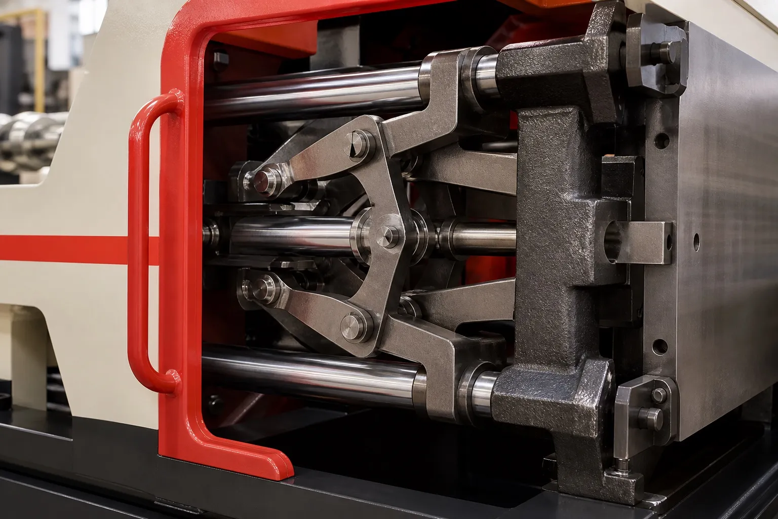
A two-cavity mould on a cable overmoulding machine pays when cooling, not loading, takes most of the cycle, and when both cavities fill alike. A horizontal clamp with injection from above suits it: two cables lie across the parting line side by side, and a short runner feeds both from the top.
The catch is balance. A runner that looks symmetrical can still deliver hotter melt to one cavity, and each cable adds its own variation. The sections below cover when the second cavity pays, why cavities fill differently and how to check them on the first trial.
Key Takeaways
- A second cavity adds parts at the cost of its loading time, so it pays most when cooling dominates the cycle.
- Even geometrically balanced runners can fill unevenly, because melt near the runner wall shears and heats more than melt in the centre.
- Check balance with hold pressure off, so every part is a little short, then weigh each cavity's part.
- Separate cable effects from runner effects by swapping cables between cavities and repeating the check.
When Does a Second Cavity Pay on a Cable Overmoulding Machine?
When the cycle is mostly cooling. The second cavity cools in the same time as the first, so it adds parts at the cost of only its loading time. If loading already takes most of the cycle, a second cavity adds less output and more strain on the operator.
Take illustrative figures: a 55 s single-cavity cycle in which loading one cable takes 8 s. A second cavity adds those 8 s, giving 63 s for two parts. Output rises from about 65 to about 114 parts per hour before rejects, roughly 75% more for one extra cable per cycle.
Loading quality matters as much as loading time. Two cables per cycle double the chances of a cable seated short of its stop or caught at a shut-off. Simple stops, guides and a cable-present check before the clamp closes keep the second cavity from becoming the main source of rejects.
Cost per part follows the same arithmetic, because the machine's hourly cost, power included, is shared over more parts. Use current rates for that sum. In Maharashtra, MERC issued an order on 25 March 2026 on MSEDCL's tariff petition after court rulings, affecting industrial tariffs from 1 July 2025, so take rates from your latest bill.
Why Do Two Identical Cavities Fill Differently?
Because melt does not stay uniform as it flows. Melt near the runner wall shears and heats more than melt in the centre, and each branch can send more of the hotter melt one way. A Plastics Technology review notes this can be felt even in two-cavity moulds.
The accepted ground rule, as that review puts it, is equal flow distance from the injection point to each cavity. Even such naturally balanced moulds can give good parts in some cavities and short shots, flash or overpacking in others. John Beaumont is quoted saying melt near the runner wall can run up to 200 °F, about 111 °C, hotter than at the centre.
Cable parts add their own sources of imbalance. If one cable is slightly thinner, its cavity holds more melt and its shut-off is looser. If one cable sits off-centre, the melt front splits unevenly around it. Both look like a runner fault but are fixed at the loading station.
Mould temperature can differ between cavities too. A cavity nearer the cooling inlet runs cooler and freezes earlier, which looks the same as a runner imbalance on the scales. Check both halves with a surface probe before blaming the steel.
How Do You Check and Fix the Balance?
Make a short shot and weigh it. RJG's Mike Groleau, quoted in the same review, suggests turning off hold pressure so that every part is at least a little short, then weighing each one. The weight difference shows the imbalance before packing hides it.
The review also quotes a working definition of balanced filling: cavity volumes within 10% to 20% of each other at 90% fill. For a soft cable part that seals at its exits, aim for the tight end of that range, because the lighter cavity is the one that shorts at a shut-off.
Fixes run from cheap to costly: equal runner lengths and diameters in steel, then gate adjustment, then valve gates or cavity sensors. A hot-runner supplier quoted in the review advises against changing gate sizes except as a last resort, because it narrows the process window.
Our view: balance a two-cavity cable mould with short shots on the first trial day, using cable from one reel in both cavities. Mixing reels during the check hides a runner fault behind cable variation, and you end up correcting steel that was right.
What Should You Check Before Ordering a Two-Cavity Mould?
Confirm the loading time per cable, the cooling time, the space for four cable exits and the clamp for two parts plus runner. Ask the mould maker for a symmetrical runner, and plan a short-shot balance check with cables swapped between cavities. See the 55 ton vertical injection moulding machine page.
Frequently Asked Questions About Two-Cavity Cable Moulds
Can I block one cavity and run the other?
Only if the mould was designed for it, with an insert that shuts off that cavity's runner cleanly. Running one cavity puts the clamp load off-centre, so check the mould maker's guidance. It is a useful fallback when one cavity is damaged, but plan the insert before the mould is built.
Should both cavities make the same part?
It is easier to balance two identical parts. A family mould with two different parts, such as a plug body and a separate strain relief, has cavities of different volume that fill at different rates. It can work for matched sets, but expect more runner correction and a narrower process window.
Is a hot runner worth it on a two-cavity PVC cable mould?
A short cold runner keeps the heat history of PVC simple and the mould easy to clean. A hot runner adds cost and places where heat-sensitive compound can sit. Use one only if the compound supplier approves it and the runner design has no dead spots where material can hang up.
How far apart should the two cavities be?
Far enough for the operator to seat both cables without crossing them, for cooling lines between the cavities, and for the cable exits to clear each other. Keep the pair centred on the platen so that clamp force is shared evenly across the mould face.
Does a two-cavity mould need a bigger machine?
Not always. Clamp roughly doubles, so check two parts plus runner at the upper tonnage factor. The shot also doubles, which can be helpful: heat-sensitive PVC prefers a shot that uses a good share of the barrel, and one small part can leave too much melt sitting hot.
Related Articles
- What Can You Make on a 55 Ton Vertical Moulding Machine?
- Heavy Cord Strain Reliefs on a 55 Ton Vertical Machine
- Wire Harness Parts: Overmoulding Clips and Grommets
Sources & References
- Plastics Technology, M. Knights: Unbalanced? No Shortage of Ways to Fix Uneven Filling of Multi-Cavity Molds (Nov 2008)
- Deccan Chamber of Commerce, Industries and Agriculture, Pune: Circular No. 085: MERC Order dated 25 March 2026 on MSEDCL Review Petition
Technical Disclaimer
Disclaimer: The information provided in this document is for general informational and educational purposes only. It is based on technical references and industry information available at the time of preparation and may be subject to change. It does not constitute engineering, technical, commercial or professional advice, nor does it constitute a quotation, specification, warranty or contractual commitment by Pratishna Engineers.
Actual injection moulding machine and process requirements vary according to the component design, material, mould, production volume, machine configuration and operating conditions. The information, examples, calculations and recommendations provided should be independently evaluated and verified for the specific application before making any equipment, process or production decision. Information obtained from third-party sources remains subject to the accuracy and limitations of those sources.
Limitation of Liability: Pratishna Engineers makes no representation or warranty, express or implied, regarding the completeness, accuracy or suitability of the information for any particular application. To the extent permitted by applicable law, Pratishna Engineers shall not be liable for any loss, damage, cost or consequence arising from reliance on or use of the information contained in this document. Final machine selection, configuration and application suitability should be confirmed with Pratishna Engineers based on complete and accurate project requirements.