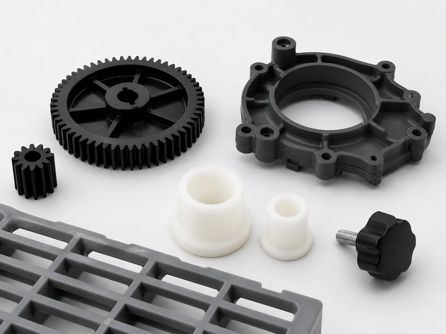
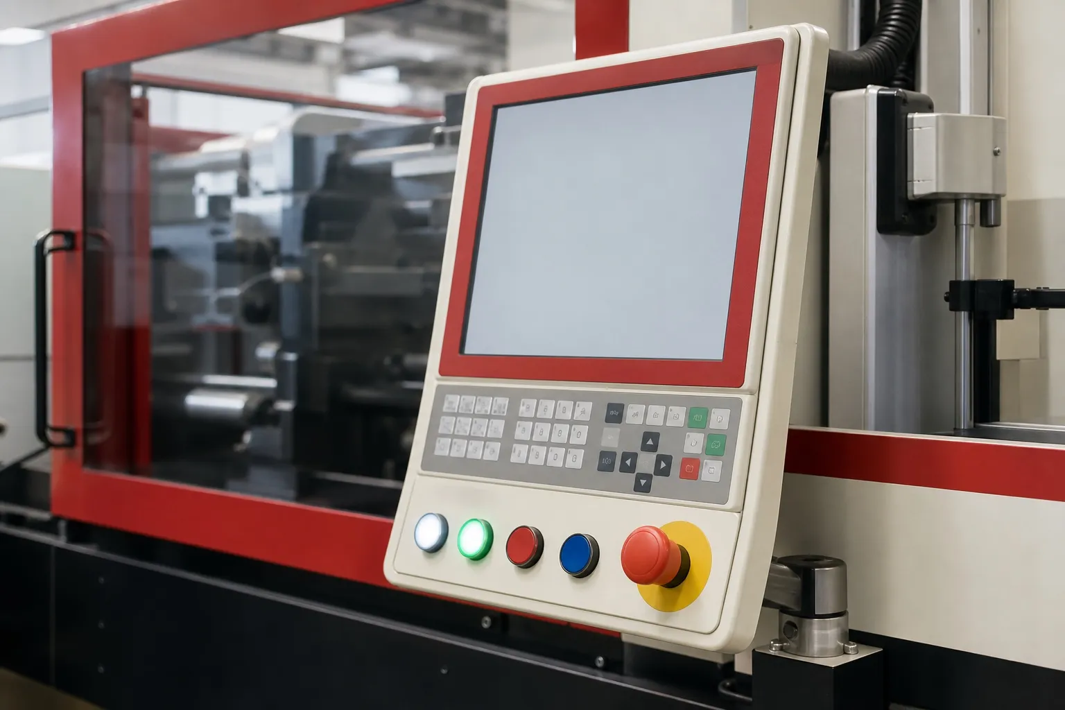
A 40 ton vertical insert moulding machine makes small parts built around a metal insert: plug pins and terminals in their carriers, lamp holder and switch contact bodies, parts with brass bushes, needle and catheter hubs, and small sensor bodies. The lower mould faces upward, so each insert sits in its pocket under gravity until the mould closes.
With a 10% reserve (a starting margin, not a rule), 40 t carries about 52 to 129 cm² of projected area, depending on the resin. A single pin carrier or needle hub uses a small fraction of that, so for small inserts the loading time and the shot size can decide the job before the clamp does.
Key Takeaways
- Typical parts are pin carriers, terminal blocks, lamp holder and switch bodies, brass-bush parts, needle hubs and small sensor bodies.
- With a 10% reserve, 40 t carries about 129 cm² at 2 US t/in² and about 52 cm² at 5 US t/in², the upper end of a PC datasheet range.
- Shot size is the second check: keep the shot within 20% to 65% of barrel capacity, worked in volume, with the insert volume left out.
- Bayonet lamp holders and switch-socket-outlets need the BIS Standard Mark under the Electrical Accessories (Quality Control) Order, 2023.
What Can a 40 Ton Vertical Insert Moulding Machine Make?
Small parts where plastic is moulded around one or a few metal inserts. Electrical work includes pin carriers, terminal blocks, lamp holder bodies and switch contact bases. Engineering and medical work includes brass-bush parts, needle and catheter hubs and small sensor housings. The table groups them by insert and resin.
Typical insert-moulded parts for a 40 t vertical machine (resins are examples; confirm each grade against the part's product standard)
| Part group | Typical insert | Example resins | What tends to limit it |
|---|---|---|---|
| Plug pins in a pin carrier | Brass pins | FR PC, PA66, PBT | Pin position and flash on contact faces |
| Terminal blocks and small connectors | Brass or copper-alloy terminals | PA66, PBT, FR PC | Number of inserts loaded per shot |
| Lamp holder and switch bodies | Brass contacts | FR PC, PA66 | Heat and fire tests on the finished part |
| Parts with threaded bushes | Knurled brass bushes | PA66, POM, ABS | Hoop stress and pull-out strength |
| Needle and catheter hubs | Stainless steel cannula | PC, PP, ABS | Cannula location and bond strength |
| Small sensor bodies | Pins or small metal housings | PBT, PA66, PC | Insert damage from melt pressure and heat |
Parts with one to four inserts per shot sit comfortably at this size. Where a part carries a dozen pins or more, the plug pins and terminals article in this series shows how loading time grows much faster than clamp demand.
Why Load Inserts Into an Upward-Facing Mould?
Because gravity holds the insert where the operator puts it. With a vertical clamp the lower mould half faces up, so a pin, bush or cannula rests in its pocket until the top half closes. A horizontal machine must hold that insert against a vertical mould face.
That holding takes extra work in the mould: tight pockets, magnets for steel inserts or spring clips. Each one adds cost and a way for an insert to drop or tilt during closing. A PlasticsToday summary of DuPont insert moulding guidance lists inserts that float or damage the mould among the main risks.
The upward-facing mould also suits two lower halves on a sliding or rotary table, so one half is loaded while the other is moulded. The loading article in this series compares those arrangements. For a first mould, a single fixed lower half keeps the tooling cost down.
Our view: moulding metal in should be a deliberate choice. The same DuPont guidance calls it a last resort and notes that inserts can often be pressed, snapped or ultrasonically fitted into a moulded part instead. Price that route before you build an insert mould.
How Much Clamp and Shot Does a Small Insert Part Use?
Clamp follows the projected area of the parts and runner times a tonnage factor, while shot follows the plastic volume, not the insert. With a 10% reserve, 40 t covers about 129 cm² at 2 US t/in² and about 52 cm² at 5 US t/in², as the table below shows.
Largest total projected area at 40 t with a 10% reserve (36.4 t usable; 1 US t/in² = 0.1406 t/cm²)
| Tonnage factor (US t/in²) | In t/cm² | Largest area at 40 t | Where this factor sits |
|---|---|---|---|
| 2 | 0.281 | 129.3 cm² | Low end, where PP and PE sit |
| 3 | 0.422 | 86.2 cm² | The starting point RJG suggests without better data |
| 4 | 0.562 | 64.7 cm² | Upper end of an ABS datasheet range (2.0 to 4.0) |
| 5 | 0.703 | 51.7 cm² | Upper end of a PC datasheet range (3.0 to 5.0) |
The method is the one Jeremy Williams of RJG sets out in Plastics Technology: projected area of one part, less through holes, times cavities, plus the full cold-runner area, times the factor. He lists flow length, wall thickness, gate size and the number of gates among the things that move it.
Shot is the second check. John Bozzelli's Plastics Technology guidance keeps the shot between 20% and 65% of barrel capacity, worked in volume with 10% added for check-valve leakage. Below 20%, melt sits in the barrel long enough to degrade. An insert fills cavity space but takes no melt, so subtract its volume.
Hand-loaded cells run long cycles, which stretches residence time further. For flame-retardant PC and nylon grades with narrow processing windows, match the barrel to the shot first and the clamp second.
Which Indian Rules Apply to Insert-Moulded Electrical Parts?
Several do. Switches to IS 3854 already need the ISI mark under a 2003 Quality Control Order. The Electrical Accessories (Quality Control) Order, 2023, S.O. 43(E) dated 1 January 2024, made the Standard Mark compulsory for bayonet lamp holders to IS 1258:2005 and switch-socket-outlets to IS 15787:2008.
The 2023 Order also covers boxes and enclosures to IS 14772:2020 and cable trunking and ducting. It came into force six months after publication, with nine months for small and twelve for micro enterprises. Goods made for export are excluded, and penalties follow the BIS Act, 2016.
For the moulder, certification lands on material choice and process control. A lamp holder body that passes the heat and fire tests in one grade may fail in another, so fix the approved grade and the regrind limit on the job sheet before production starts.
What Should You Send for a 40 t Fit Check?
Send the part drawing with the insert drawing, the number of inserts per shot, the resin grade, part weight, target cavities and hourly output. Mark through holes and the insert faces that must stay clean. Clamp, shot and loading can then be checked together. See the 40 ton vertical injection moulding machine page.
Frequently Asked Questions About 40 Ton Vertical Insert Moulding
Can a 40 t vertical machine run parts without inserts?
Yes. A vertical machine moulds plain parts too, though the upward-facing mould and the loading space bring no benefit then. If plain parts will fill most of its hours, compare it with a horizontal machine, which can drop parts onto a conveyor and run without an operator at the mould.
How many inserts can one operator load per shot?
It depends on insert size, how tightly the inserts fit their pockets and whether each one must be checked. Time an operator loading real inserts into a sample fixture before you fix the cavity count. The plug pins and terminals article in this series works through the effect of insert count on cycle time.
Which resin should I choose for an insert-moulded electrical part?
Start from the product standard and the tests the finished part must pass, then pick a grade with data for them. One flame-retardant PC datasheet lists UL 94 V-0 at 3.0 mm and a glow-wire flammability index of 960 °C at 1.5 and 3.0 mm. Check every rating at your own wall thickness.
Can the same machine run electrical and medical insert parts?
Mechanically, yes, but medical parts bring cleanliness, traceability and documentation demands that an electrical job may not. Plan a separate clean area and dedicated material handling before taking on needle or catheter hubs. The needle hub article in this series covers cannula location, bond strength and the rules that apply.
Is a 40 t clamp enough for a part with a large metal insert?
Clamp depends on the plastic's projected area, not the insert's size, so a large insert can still fit 40 t. Check the open height for loading, the lower mould size against the table and the insert weight the operator handles each cycle. A heavy insert may also need preheating to avoid chilling the melt.
Related Articles
- Moulding Plug Pins and Terminals on a 40 Ton Vertical Machine
- Needle Hubs on Vertical Machines: Insert Location and Bond Strength
- Small Insert Moulding Cells: Manual or Automated Loading?
Sources & References
- Plastics Technology, J. Williams (RJG): Clamp Tonnage: More Is Better...Right?
- Plastics Technology, J. Bozzelli: A Simpler Way to Calculate Shot Size vs. Barrel Capacity
- PlasticsToday, summarising A. Miller (DuPont): Design and material advice from the pros, Part 3: Insert molding essentials
- Gazette of India (DPIIT): Electrical Accessories (Quality Control) Order, 2023, S.O. 43(E)
Technical Disclaimer
Disclaimer: The information provided in this document is for general informational and educational purposes only. It is based on technical references and industry information available at the time of preparation and may be subject to change. It does not constitute engineering, technical, commercial or professional advice, nor does it constitute a quotation, specification, warranty or contractual commitment by Pratishna Engineers.
Actual injection moulding machine and process requirements vary according to the component design, material, mould, production volume, machine configuration and operating conditions. The information, examples, calculations and recommendations provided should be independently evaluated and verified for the specific application before making any equipment, process or production decision. Information obtained from third-party sources remains subject to the accuracy and limitations of those sources.
Limitation of Liability: Pratishna Engineers makes no representation or warranty, express or implied, regarding the completeness, accuracy or suitability of the information for any particular application. To the extent permitted by applicable law, Pratishna Engineers shall not be liable for any loss, damage, cost or consequence arising from reliance on or use of the information contained in this document. Final machine selection, configuration and application suitability should be confirmed with Pratishna Engineers based on complete and accurate project requirements.