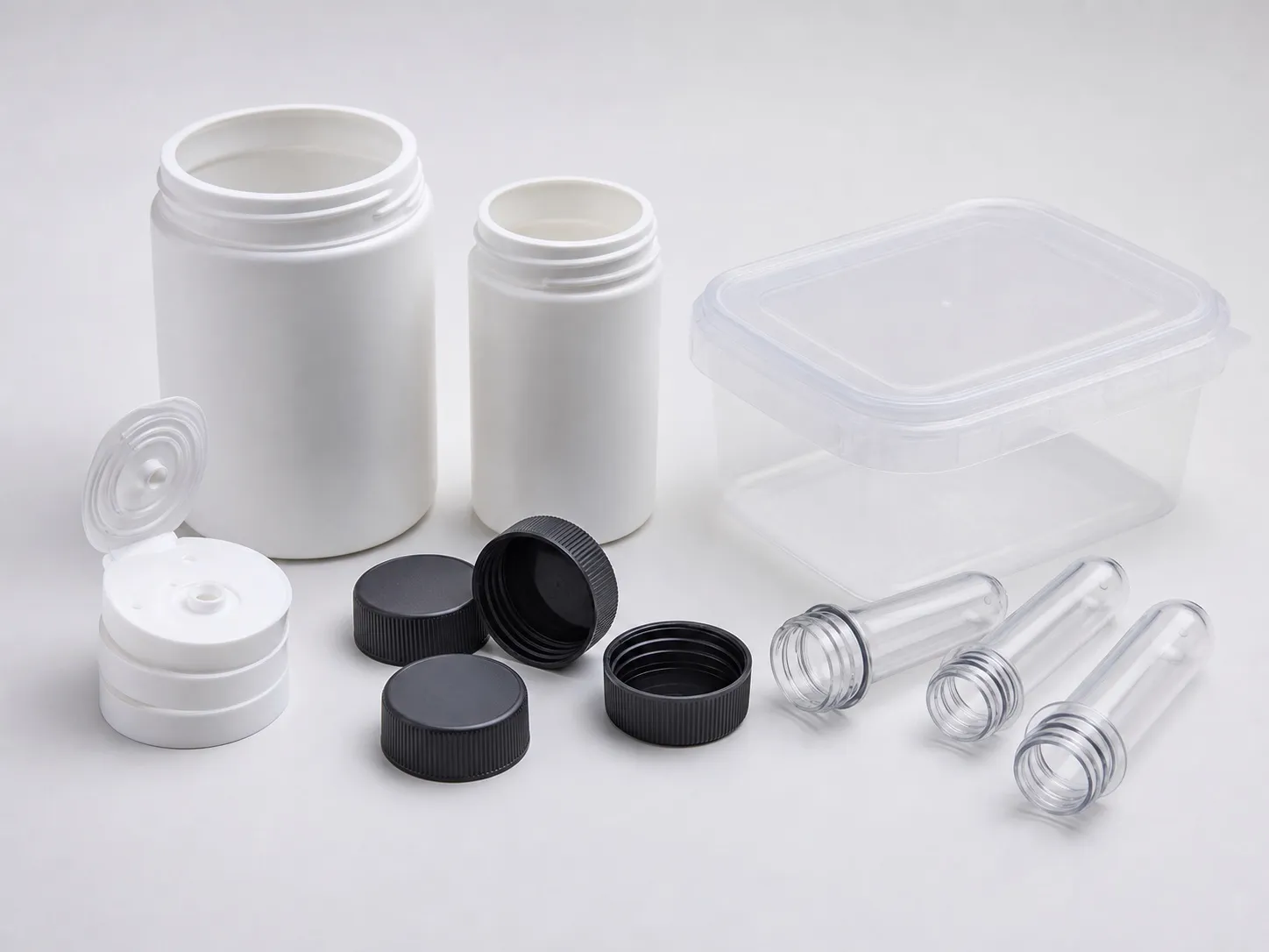
Take a flat PP tray measuring 300 × 240 mm. Its projected area is 720 cm². At a factor of 2 US t/in² (0.281 t/cm²) it needs 202 t, or 223 t with a 10% reserve (a starting margin, not a rule). At 2.5 US t/in² it needs 278 t. On a 250 t machine, flash control on large flat parts starts with that narrow margin.
Large flat parts sit close to the clamp limit, spread the load across most of the platen and give melt a long, thin path to the edges. Flash appears where the mould opens first. Balanced clamping, correct mould size, sound vents and a steady process control it; extra tonnage usually does not.
Key Takeaways
- A 300 × 240 mm PP tray fits 250 t only if the tonnage factor stays at or below about 2.2 US t/in².
- A mould should cover at least about 70% of the distance between the tie bars, or the platens can bow and flash the centre.
- Over-clamping crushes vents and cracks steel, and the trapped gas it causes can make filling worse.
- Flash at the edge, centre or one corner each points to a different cause, so map it before changing settings.
Why Do Large Flat Parts Flash More Easily?
Because they use most of the clamp and most of the platen at once. A thin, wide part needs high pressure to fill its far edges, the force opening the mould acts over a large face, and any bending of platens or plates opens a gap.
RJG's John Williams, writing in Plastics Technology, lists flow length, wall thickness, gate location and the number of gates among the factors that set the tonnage factor. A flat lid gated at one edge has a far longer flow than the same lid gated in the centre, so it needs more pressure and more clamp.
Polymer choice matters too. Reliance lists Repol H200MA, a PP homopolymer with an MFR of 25 g/10 min, for thin-walled containers, multicavity moulding and long flow paths. A high-flow grade fills at lower pressure, but a thinner melt also slips into a gap more readily, so it is no cure on its own.
Wall thickness works the same way. A thinner wall cools faster and saves cycle time, but it narrows the flow channel, so the pressure needed at the gate climbs. On a part that already sits near the clamp limit, a small cut in wall can be enough to tip it into flash. Change wall and gating together, and recalculate the clamp each time.
How Does Balanced Clamping Stop Flash in the Middle?
By making sure the clamp force reaches the whole parting line evenly. That depends on a mould large and stiff enough to spread the load across the platens, centred on the platen, and supported inside so the plates under the cavity do not deflect.
A Plastics Technology article on mounting moulds, by P. Witaszek and co-authors including John Bozzelli, gives a rule of thumb that the mould should cover at least 70% of the distance between the tie bars. Smaller moulds let the platens bow under clamp, which causes flash in the mould centre, and very small moulds can cause catastrophic platen damage.
Where flash appears on a flat part and what to check first
| Flash location | Likely cause | Check first |
|---|---|---|
| Centre of the part | Platens or mould plates bowing | Mould size against the tie-bar gap; support pillars under the cavity |
| One side or corner | Mould off centre or platens out of parallel | Mould centring on the platen; parallelism |
| Far edges, at end of fill | Pressure peak at transfer; high early hold | Transfer position and hold profile |
| Around the vents | Vents too deep or worn | Vent depth against the resin supplier's range |
| All round the parting line | Clamp too low for the area and factor | Recalculate clamp; check the factor used |
Support pillars between the ejector housing and the moving clamp plate carry the load under the cavity. Our view: on any flat part above about half the clamp's area limit, ask the mould maker to show the pillar layout on the drawing before the steel is ordered.
Is More Clamp the Answer to Flash Control on Large Flat Parts?
Rarely. Raising clamp toward the maximum may stop flash for a while, but it compresses vents and stresses the mould and machine. Williams describes a mould that needed about 100 tons being clamped at a 400-ton machine maximum; the cavity block split in two places, costing upwards of $100,000.
He lists other effects of over-clamping: burns, short shots, gloss changes, crushed vents, a rolled parting line and broken inserts. The burns and short shots come from gas trapped behind crushed vents, which then tempts the setter to raise pressure, and higher pressure brings the flash back.
Vents need the same care. S. Shannon's MoldMaking Technology article says vent depth has no fixed number; resin suppliers give a range, for PP about 0.013 to 0.051 mm. Moldmakers usually cut at the low end, and the moulder deepens in steps of about 0.005 to 0.008 mm until whisker flash appears, then backs off one step.
Shannon also notes that repeated clamping can coin vents shut, so check both halves, and that vents and land widths must be identical cavity to cavity. Process settings matter as well: a pressure peak at transfer or a high hold at the start of packing pushes melt into any gap the clamp leaves.
What Should You Send for a Flash Review?
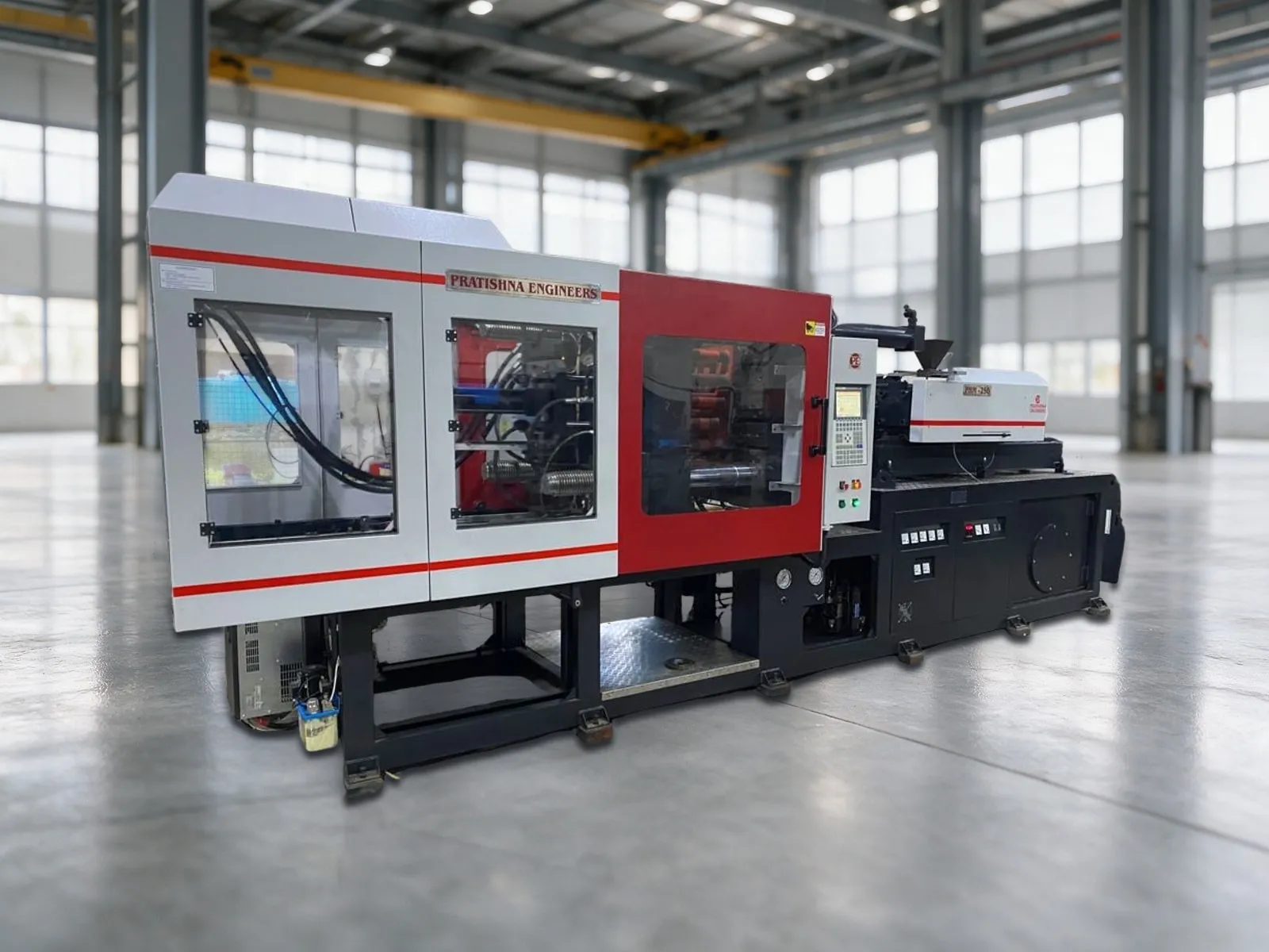
Send the part outline, wall, flow length from each gate, resin grade, the mould's outside size and a photo or sketch showing where the flash appears. Clamp, mould size against the tie-bar gap and support can then be checked together. See the 250 ton two platen injection moulding machine page.
Frequently Asked Questions About Flash on Large Flat Parts
Can a mould be too small for the machine?
Yes. If the mould covers much less than about 70% of the distance between the tie bars, the platens can bow under clamp and the mould centre can flash. Very small moulds can damage the platens. Check the minimum mould size in the machine manual or on its frame placard.
Why does flash appear only after the mould warms up?
As the mould heats, the steel expands, and on some clamps the set mould height no longer matches, which changes the effective clamp at the parting line. Melt viscosity also falls as the barrel and hot runner settle. Recheck clamp and mould height once the mould reaches running temperature.
Does centre gating reduce flash on a flat lid?
Often, because it shortens the longest flow path and evens out the pressure needed to fill each edge. A lid gated from one side needs higher pressure to reach the far edge, which raises the force opening the mould. Mould-filling analysis can confirm the best gate position.
How do I know whether flash is a clamp problem or a mould problem?
Lower the injection speed and transfer pressure slightly and watch the flash. If it shrinks at the same clamp, the process was pushing too hard. If flash stays in one spot regardless, look for a damaged parting line, worn vents or a deflecting plate in the mould.
Does a two-platen machine give more even clamping than a toggle?
Some builders claim that direct hydraulic clamping gives more uniform pressure, while toggles apply force near the platen corners. These are reported claims, not test results. Whatever the clamp type, mould size, support and platen parallelism decide whether the force reaches the centre of a flat part.
Related Articles
- What Can You Make on a 250 Ton Two Platen Machine?
- Battery Containers and Appliance Housings on a 250 Ton Machine
- Moulding Plastic Stools on a 250 Ton Two Platen Machine
Sources & References
- Plastics Technology, P. Witaszek, J. Klees, J. Fattori, E. Di Siro, J. Bozzelli: How to Mount an Injection Mold (June 2017)
- Plastics Technology, J. Williams (RJG): Clamp Tonnage: More Is Better...Right?
- MoldMaking Technology, S. Shannon: How to Determine the Proper Vent Depth
- Reliance Industries: Repol H200MA technical data sheet (July 2024)
Technical Disclaimer
Disclaimer: The information provided in this document is for general informational and educational purposes only. It is based on technical references and industry information available at the time of preparation and may be subject to change. It does not constitute engineering, technical, commercial or professional advice, nor does it constitute a quotation, specification, warranty or contractual commitment by Pratishna Engineers.
Actual injection moulding machine and process requirements vary according to the component design, material, mould, production volume, machine configuration and operating conditions. The information, examples, calculations and recommendations provided should be independently evaluated and verified for the specific application before making any equipment, process or production decision. Information obtained from third-party sources remains subject to the accuracy and limitations of those sources.
Limitation of Liability: Pratishna Engineers makes no representation or warranty, express or implied, regarding the completeness, accuracy or suitability of the information for any particular application. To the extent permitted by applicable law, Pratishna Engineers shall not be liable for any loss, damage, cost or consequence arising from reliance on or use of the information contained in this document. Final machine selection, configuration and application suitability should be confirmed with Pratishna Engineers based on complete and accurate project requirements.