






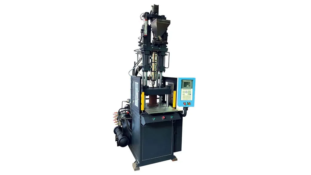

An injection moulding machine for drip irrigation makes small, multi-cavity parts in PP and PE: emitters, connectors, offtakes, valves and sprinkler bodies. The table maps each part family to its Indian Standard and to the machine feature that matters most.
Micro-irrigation parts, BIS standards and machine focus
| Part | Indian Standard | Machine focus |
|---|---|---|
| Emitters (inline and online) | IS 13487:2024 | Multi-cavity balance, fine shot control |
| Emitting pipes and fittings | IS 13488:2008 | Small shots, short cycles |
| Micro sprayers | IS 14605:1998 | Small orifices, flash-free parting lines |
| Rotating sprinklers | IS 12232 Part 1 | Moving parts, dimensional repeatability |
| Quick-coupled PE pipes and fittings, 40 to 200 mm OD | IS 17425:2020 | Larger shots, thicker walls |
| Manually operated plastics valves, DN 8 to DN 110 | IS 18286:2023 | Larger clamp, core pulls |
For emitters and small fittings the clamp is small and the mould is the hard part. The machine must fill many tiny cavities alike, shot after shot, because an emitter that passes more or less water than its rating fails the field uniformity it was bought for. Larger valves and couplers belong on a separate, bigger press.
Key Takeaways
- Emitters and small fittings run in high-cavity moulds, so cavity balance and shot repeatability matter more than clamp tonnage for this work.
- IS 13487:2024 covers inline and online emitters, regulated and unregulated, with uniformity categories A and B; know which category your customer sells.
- PP and PE are semi-crystalline, so their shrinkage is higher and more sensitive to moulding conditions than amorphous resins; hold mould temperatures steady.
- Valves and quick-coupled fittings need a bigger machine than emitters; one press rarely suits both a 32-cavity emitter mould and a DN 110 valve.
What does an injection moulding machine for drip irrigation need?
It needs fine control of small shots, fast and repeatable injection into many cavities, stable mould temperature control and enough platen area for a high-cavity mould. Clamp force is usually modest, so check the tie-bar spacing and mould height range before the tonnage figure.
Platen space is easy to underestimate. A rule of thumb is that the mould should cover at least 70% of the distance between the tie bars, because a small mould on a large platen lets the platens bow under clamp and flash appears in the mould centre. An emitter mould can be wide but light, so check both size and weight limits.
Shot repeatability matters because the shot is split many ways. Keep the shot between 25% and 65% of barrel capacity. Below about 25%, melt uniformity is often poor, and below about 20%, residence time grows and the melt can degrade, which shows up as uneven filling and discoloured parts.
Our view: for emitter work, match the screw to the shot first and accept the clamp that comes with it. A press bought for tonnage will run these moulds with a barrel that is far too large.
Cooling water deserves the same care. Emitter cycles are short, so a chiller that cannot hold mould temperature through a hot afternoon in May will show up as drifting part weights and dimensions long before anyone suspects the machine.
How do you keep a multi-cavity emitter mould balanced?
Start with a naturally balanced runner, then prove it. Turn off hold pressure, run short shots so every cavity is slightly unfilled, and weigh the parts by cavity. A common target is that cavity fill varies by no more than 10% to 20% at 90% fill.
Equal flow distance is not enough. Shear heating makes the melt near the runner wall hotter than the centre, so in a geometrically balanced runner some cavities can still fill first. The coolest, slowest cavity then sets the injection pressure for the whole shot, and the fastest cavity flashes or overpacks.
Fixes run from runner layout changes to hot runners with individual zone control. Changing gate sizes to force balance is best left as a last resort, because it narrows the process window. On flat emitters, each cavity also needs equal cooling, or labyrinth dimensions will drift from cavity to cavity.
Venting is the quiet cause of trouble. Vents should be identical cavity to cavity, and repeated clamping can coin them shut, so check vent depth on both mould halves during planned maintenance and after any flash complaint.
Which PP and PE grades suit irrigation parts?
Choose by part. High-flow PP homopolymer suits thin, multi-cavity parts with long flow paths; impact copolymers suit fittings and valve bodies that must survive handling and field impact; PE suits flexible and pipe-mating parts. Confirm UV stabilisation and any customer or standard requirement for carbon black.
Indian grade data sheets give you a starting window. One PP homopolymer sold for thin-walled containers, multi-cavity moulding and long flow paths lists an MFR of 25 g/10 min, melt temperature 210 to 250 °C and mould temperature 20 to 50 °C. Use that window as the starting point for barrel settings.
Shrinkage needs attention. Published mould shrinkage for PP runs from 1.0% to 2.5% and for PE from 1.5% to 4.0%, and both move with melt temperature, cooling rate, wall thickness and gate size. For parts that must seal on a pipe, hold mould temperature tight and measure parts only after they have cooled fully.
The laterals themselves are extruded, not moulded. IS 12786:2024 covers PE lateral pipes of 12 to 32 mm OD, and your moulded fittings and offtakes must grip and seal on them across the full tolerance band.
What should you prepare before buying a machine for irrigation parts?
List each part with its standard, resin grade, weight, cavity count and annual volume, then group parts by size so one machine is not asked to do everything. Share mould layouts early. See the agriculture and irrigation solutions page for related applications.
Frequently Asked Questions About Drip Irrigation Part Moulding
Can one machine make emitters and sprinkler bodies?
Sometimes, if the shot and platen sizes overlap, but the two jobs pull apart. Emitters need small, fast, repeatable shots into many cavities, while sprinkler bodies and valves need larger shots, core pulls and more opening stroke. Grouping parts by size and giving each group its own machine keeps scrap and changeovers down.
Why do some emitter cavities flash while others short?
That is a filling imbalance. Shear heating in the runner sends hotter, thinner melt to some cavities first, so they overpack or flash while the slowest cavity is still filling. Weigh short shots by cavity to measure it, then correct the runner or the hot runner zones rather than raising pressure.
Do emitter moulds need a hot runner?
Not always. A cold runner is simpler and copes better with recycled feedstock, where small metal pieces can plug hot runner tips, while a hot runner cuts waste and can improve balance with zone control. Decide from cavity count, resin cost, regrind policy and maintenance skill, and ask your mould maker for both layouts.
Which Indian Standard covers drip emitters?
IS 13487:2024 covers emitters, both inline and online, regulated and unregulated, with uniformity categories A and B. Related standards cover emitting pipes (IS 13488), micro tubes (IS 14482), micro sprayers (IS 14605) and drip blockage (IS 14791:2024). Check the BIS compendium for the current edition before you fix part tolerances.
What cycle time should I plan for drip emitters?
There is no single figure. Cycle time follows the thickest wall, mould cooling and the ejection method, so it changes with emitter design. Measure cooling on your own mould, add about 20% to the calculated cooling timer as a safety factor, and plan output on a conditional range rather than a promised number.
Related Articles
- Injection Moulding Machine for Caps & Closers
- Injection Moulding Machine for Medical & Science
- Plastic Injection Machine: Revolutionizing Mass Production
- Injection Moulding Machine for Household Items
Sources & References
- BIS: Compendium of Indian Standards: Micro-Irrigation Systems
- Plastics Technology, M. Knights: Unbalanced? No Shortage of Ways to Fix Uneven Filling of Multi-Cavity Molds (Nov 2008)
- LyondellBasell: Technical Tip: Mold Shrinkage
- Reliance Industries: Repol H200MA Technical Data Sheet (July 2024)
Technical Disclaimer
Disclaimer: The information provided in this document is for general informational and educational purposes only. It is based on technical references and industry information available at the time of preparation and may be subject to change. It does not constitute engineering, technical, commercial or professional advice, nor does it constitute a quotation, specification, warranty or contractual commitment by Pratishna Engineers.
Actual injection moulding machine and process requirements vary according to the component design, material, mould, production volume, machine configuration and operating conditions. The information, examples, calculations and recommendations provided should be independently evaluated and verified for the specific application before making any equipment, process or production decision. Information obtained from third-party sources remains subject to the accuracy and limitations of those sources.
Limitation of Liability: Pratishna Engineers makes no representation or warranty, express or implied, regarding the completeness, accuracy or suitability of the information for any particular application. To the extent permitted by applicable law, Pratishna Engineers shall not be liable for any loss, damage, cost or consequence arising from reliance on or use of the information contained in this document. Final machine selection, configuration and application suitability should be confirmed with Pratishna Engineers based on complete and accurate project requirements.

