







Take a small PP part on a 12 s cycle with 97% good shots. An 8-cavity mould gives about 2,328 parts an hour (3,600 ÷ 12 × 8 × 0.97); a 16-cavity mould on the same cycle gives about 4,656. That doubling is the case for multi cavity moulding for mass production. It holds only if every cavity fills alike, the clamp covers the full projected area including any runner, and the shot and injection rate suit the whole layout. Get those right and output scales with cavities; get them wrong and the extra cavities add short shots, flash and sorting.
Key Takeaways
- Size the clamp for every cavity plus any cold runner area; with a hot runner, only the cavities count toward projected area at the parting line.
- Equal flow length to each cavity does not guarantee balance; shear heating in the runner can make inner and outer cavities fill differently.
- Check balance with hold pressure off, so every part is slightly short, then weigh each cavity's part and compare the spread.
- Choose a high-flow resin grade suited to multicavity work, and confirm the shot sits in a healthy share of barrel capacity for the whole layout.
How do you size clamp force for multi cavity moulding for mass production?
Multiply the projected area of one part by the number of cavities, add the full cold runner area, then multiply by a tonnage factor for the material. Add a modest reserve. With a hot runner, count only the cavities, because the hot runner sits behind the parting line.
Subtract any through holes or cored-out areas from the part's projected area before multiplying. Typical tonnage factors run from 2 to 10 US tons per square inch, and one widely cited method suggests 3 as a starting point. For PP the factor is usually 2 to 3, which is about 0.281 to 0.422 t per cm².
Add a reserve of about 10%, as a starting margin, not a rule. Thin walls, long flow paths and stiff resins push the factor up, while short flow and easy-flowing grades bring it down. Melt flow index, wall thickness, flow length, gate size and the number of gates all move the factor.
Do not answer a flash problem by clamping at the machine's maximum. One published case describes a mould needing about 100 t that was clamped at 400 t; the cavity block split in two places. Over-clamping also crushes vents and rolls the parting line, which makes balance worse, not better.
Cold runner and hot runner in a multi-cavity mould
| Point | Cold runner | Hot runner |
|---|---|---|
| Counts toward clamp area | Cavities plus full runner area | Cavities only |
| Material per shot | Parts plus runner to regrind | Parts only |
| Balance tuning | Runner sizes changed in steel | Nozzle and manifold temperatures trimmed |
| Colour change | Runner clears with each shot | Manifold needs purging |
Why do naturally balanced runners still fill unevenly?
Because melt does not flow through a runner as a uniform mass. Material near the runner wall is sheared and heated more than the core, and at each branch the hotter, less viscous layer can be steered toward some cavities. Those cavities fill first even when flow lengths are equal.
The accepted ground rule is equal flow distance from the sprue to each cavity, yet so-called naturally balanced moulds still give good parts in some cavities and short shots or flash in others. A trade review cites research showing melt near the runner wall can run up to about 111 °C hotter than the centre, with viscosity differing by orders of magnitude.
The coolest, slowest-filling cavity sets the injection pressure the whole mould needs. The cavities that fill first are then overpacked while the last one is still filling. That is how one mould can produce flash, sinks and short shots in the same shot, and why size differences often track cavity position.
Resin choice helps. Indian PP grades are made for this duty: Reliance's Repol H200MA, for example, is listed for thin-walled containers, multicavity moulding and long flow paths, with an MFR of 25 g/10 min and a melt temperature of 210 to 250 °C. A higher-flow grade narrows the pressure gap between the first and last cavity, though it does not remove the shear effect.
How do you check filling imbalance before full production?
Turn off hold pressure and reduce the shot so every cavity is slightly short, then weigh each part by cavity number. The heaviest cavities fill first. Compare the spread over several shots; a consistent pattern points to the runner or gates, while random scatter points to process or machine.
This short-shot weighing method is recommended by RJG for assessing imbalance. Balanced filling is commonly taken as cavity volumes varying by no more than 10% to 20% at about 90% fill. Keep cavity numbers marked on every part, and file the weighed samples with the trial report so later changes can be compared.
Fix the cause in order. First check that cavity steel, vents and cooling match from cavity to cavity; vents and land widths should be identical. Then look at runner layout. Varying gate sizes to force balance is advised against except as a last resort, because it narrows the process window, and sequential valve gating is an expensive fix.
Do not add cavities to a mould that has not passed a short-shot balance check. Once balance is proven, size the shot for the full layout in volume, not in polystyrene grams, and confirm it sits in a healthy share of the barrel.
What should you send before adding cavities?
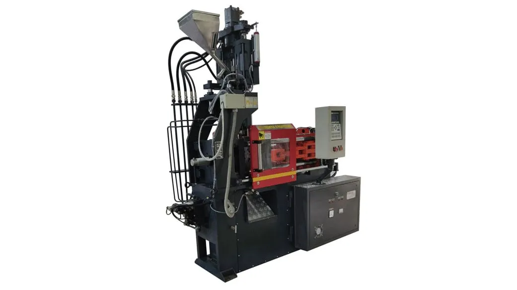
Send the part drawing, material grade, target output per hour, and short-shot weights by cavity from the current mould if you have them. With those, the clamp, shot and injection rate for the new layout can be checked before steel is cut. See the injection moulding machine range for sizes.
Frequently Asked Questions About Multi-Cavity Moulding
How many cavities can one mould have?
There is no fixed number. The limit comes from clamp force, tie-bar space, shot volume, injection rate and how well the runner can balance flow to every cavity. Small parts on balanced hot runners can run with many cavities; large or complex parts may justify only two or four.
Does a hot runner reduce the clamp force needed?
Yes, in most layouts. With a cold runner, the full runner area at the parting line adds to the projected area, so it adds clamp force. With a hot runner only the cavities count. The saving depends on how large the cold runner would have been compared with the parts.
What imbalance between cavities is acceptable?
A common working figure is cavity fill volumes varying by no more than 10% to 20% at about 90% fill, measured by weighing short shots with hold off. Tighter-tolerance parts need a smaller spread. Agree the limit with your quality team before trials so the result is judged against a set number.
Should I enlarge gates to balance filling?
Only as a last resort. Changing gate sizes can force cavities to fill together at one setting, but it narrows the process window, so small changes in material or temperature upset the balance again. Check steel, vents, cooling and runner layout first, and keep gates identical where possible.
Does adding cavities change the barrel size I need?
Yes. The shot grows with every cavity and with the runner, so recalculate it in volume for the new layout. Machine ratings are usually in grams of polystyrene, and PP is less dense in the melt, so convert before comparing. Keep the shot within roughly 20% to 65% of barrel capacity.
Related Articles
- Plastic Injection Molding Machine: Enhancing Efficiency and Precision in Manufacturing
- Injection Moulding Machine: Enhancing Efficiency and Productivity
- Why Automatic Injection Moulding Machines Are Perfect for Mass Production
- Injection Moulding Machine for Caps and Closures
Sources & References
- Plastics Technology, J. Williams (RJG): Clamp Tonnage: More Is Better...Right? (May 2017)
- Plastics Technology, M. Knights: Unbalanced? No Shortage of Ways to Fix Uneven Filling of Multi-Cavity Molds (Nov 2008)
- SPE Plastics Engineering, A. Urbina: Mastering Clamping Force Calculation (Mar 2024)
- Reliance Industries: Repol H200MA Technical Data Sheet (July 2024)
Technical Disclaimer
Disclaimer: The information provided in this document is for general informational and educational purposes only. It is based on technical references and industry information available at the time of preparation and may be subject to change. It does not constitute engineering, technical, commercial or professional advice, nor does it constitute a quotation, specification, warranty or contractual commitment by Pratishna Engineers.
Actual injection moulding machine and process requirements vary according to the component design, material, mould, production volume, machine configuration and operating conditions. The information, examples, calculations and recommendations provided should be independently evaluated and verified for the specific application before making any equipment, process or production decision. Information obtained from third-party sources remains subject to the accuracy and limitations of those sources.
Limitation of Liability: Pratishna Engineers makes no representation or warranty, express or implied, regarding the completeness, accuracy or suitability of the information for any particular application. To the extent permitted by applicable law, Pratishna Engineers shall not be liable for any loss, damage, cost or consequence arising from reliance on or use of the information contained in this document. Final machine selection, configuration and application suitability should be confirmed with Pratishna Engineers based on complete and accurate project requirements.

