






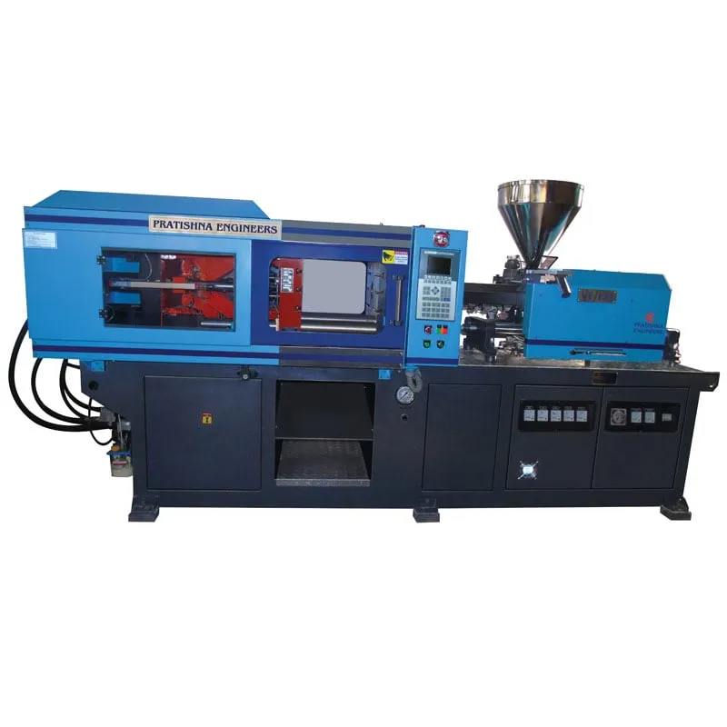

Take a 22.4 second cycle on a four-cavity PP part: about 14 seconds of it is cooling, and only about 4 seconds is the mould moving. That split explains injection moulding machine parts and working better than any diagram. The machine has four main units. The clamp unit closes, locks and opens the mould. The injection unit melts the resin and pushes it in. The hydraulic system, or servo and electric drives, powers every movement. The controller sequences all of it and holds each setting to the same value, shot after shot. Each unit is sized against your part, resin and mould.
Key Takeaways
- The clamp unit holds the mould shut against melt pressure, so its rating follows the projected area of parts and runner, not the part weight.
- The injection unit melts resin mostly through screw shear, and a shot of 25% to 65% of barrel capacity keeps the melt consistent.
- Hydraulic pumps, servo pumps or electric motors drive the movements, and on a hydraulic machine the pump motor is the largest energy user.
- In many parts cooling takes the largest share of the cycle, so wall thickness often decides cycle time more than machine speed does.
What are the injection moulding machine parts and working stages?
An injection moulding machine has four working units: the clamp unit that closes and locks the mould, the injection unit that melts and injects the resin, the drive system that powers both, and the controller that sequences them. Every cycle runs the same six stages.
The six stages of one moulding cycle
| Stage | Unit doing the work | What to watch |
|---|---|---|
| 1. Close and lock | Clamp unit | Slow down before the parting line; build full tonnage |
| 2. Inject (fill) | Injection unit | Fill speed and the switch point to hold |
| 3. Hold (pack) | Injection unit | Hold pressure and time until the gate freezes |
| 4. Cool and recover | Mould cooling; screw rotates back | Recovery must finish inside the cooling time |
| 5. Open | Clamp unit | Opening stroke long enough to release the part |
| 6. Eject | Ejector system | Ejection without marks, sticking or distortion |
The clamp closes the mould at speed, slows near the parting line to protect it, then builds tonnage. The injection unit pushes melt in under speed control, switches to pressure control and keeps the cavity packed while the gate freezes. Cooling starts the moment melt touches the steel.
While the part cools, the screw rotates and slides back, metering the next shot in front of its tip. This recovery has to finish inside the cooling time, or the whole cycle waits for the screw. Once the part is stiff enough, the clamp opens and the ejectors push it off the core.
On a hydraulic machine each stage is a valve and pump command; on an electric machine each is a servo motor move. The order of the six stages does not change.
RJG notes that only about 40% of the heat must be removed before ejection, and it recommends adding about 20% to the calculated cooling time as a safety factor. Treat that margin as a starting point you can trim once parts measure well and stay stable.
How does the clamp unit hold the mould shut?
The clamp unit holds the mould closed with a force larger than the melt pressure acting on the projected area of the parts and runner. Toggle clamps multiply a cylinder's force through linkages, while hydraulic and two-platen clamps apply force directly through cylinders on the platen.
Tonnage comes from projected area multiplied by a tonnage factor that depends on resin, wall and flow length. Plastics Technology gives typical factors of 2 to 10 US tons per square inch and suggests 3 as a first figure. In metric terms, 3 US tons per square inch is about 0.42 t/cm².
More clamp is not safer. Plastics Technology lists crushed vents, a rolled parting line and broken inserts among the effects of over-clamping, and reports a mould needing about 100 tons that split its cavity block when clamped at 400 tons.
Tie bar spacing, minimum and maximum mould height, opening stroke and ejector stroke decide whether the mould physically fits. Our view is flat: check mould fit before tonnage, because a mould that sits badly on the platens will flash or wear at any tonnage you set.
How do the injection unit and drives turn pellets into a shot?
The injection unit melts pellets mainly through shear from the rotating screw, with barrel heaters adding the rest. The screw then acts as a plunger and injects the metered melt. Hydraulic pumps, servo-driven pumps or electric motors supply the force and speed for every movement.
Plastics Technology puts a healthy shot at 25% to 65% of barrel capacity. Below that range the melt sees too few screw turns; above it, unmelts and slow recovery appear. Shot ratings are usually given in grams of polystyrene, so convert your resin by melt density before you compare machines.
Pressure at the nozzle is hydraulic pressure multiplied by the intensification ratio, the ram area divided by the screw area. A smaller screw on the same unit gives more pressure and less volume, which is why a second barrel size can rescue a hard-to-fill mould.
On a hydraulic machine the main motor is the largest energy user, and older fixed-pump machines keep drawing power between movements. In Maharashtra, MSEDCL bills HT and larger LT industrial connections on kVAh, so a poor power factor from motors also shows on the bill. The controller holds temperatures, speeds, pressures and positions to setpoint every cycle.
Modern controllers also store mould recipes, so a repeat job starts from saved settings instead of memory. That shortens setup and cuts the scrap made while an operator hunts for the old process window. Ask to see the recipe screen and alarm history during any machine trial.
What should you check before you shortlist a machine?
Write down the part drawing, resin grade, cavities, shot weight and target output. Then check each unit against them: clamp and mould fit, shot inside the barrel window, drive type for your running hours. Send those figures to every maker you shortlist. See the injection moulding machine range.
Frequently Asked Questions About Injection Moulding Machine Parts and Working
What is the difference between a toggle clamp and a hydraulic clamp?
A toggle clamp uses linkages to multiply a cylinder's force and lock the mould mechanically. Suppliers quoted by Plastics Technology report that toggles lock slightly faster and give greater opening force, while direct hydraulic clamps give finer pressure control and a wider mould height range. Choose on your mould and part, not on habit.
Why does the screw move back during the cycle?
The screw rotates to melt and convey resin forward, and that melt collects in front of the tip and pushes the screw back. The distance it travels sets the shot volume. Back pressure resists this movement to improve mixing, and the whole recovery has to finish within the cooling time.
What does the controller on an injection moulding machine do?
The controller runs the cycle sequence and holds every setpoint: barrel zone temperatures, injection speeds, switch-over position, hold pressure and time, clamp speeds and positions. It also logs alarms and cycle data. Fine control resolution matters most on thin walls and tight tolerances, where small drifts show up as short shots or size changes.
How is shot size on a machine rated?
Shot size is usually rated in grams of polystyrene. Because PS melt density is about 0.945 g/cm³ and PP about 0.74 g/cm³, the same barrel holds about 22% less PP by weight. Convert your part and runner weight to melt volume, add about 10%, then compare against the barrel.
Which stage of the cycle takes the longest?
Cooling usually takes the longest, because cooling time grows with the square of wall thickness. A wall 20% thinner needs about 36% less cooling time. In RJG's trial on an 8-cavity ABS bar 3.3 mm thick, about 85% of the cycle was cooling, so mould cooling design pays back faster than faster clamp speed.
Related Articles
- Injection Moulding Machine for Construction Tiles
- Injection Moulding Machine for Shipping Pallets
- Types of Injection Moulding Machines
- The Essential Role of Injection Molding Machines in Manufacturing
Sources & References
- Plastics Technology, J. Williams (RJG): Clamp Tonnage: More Is Better...Right?
- Plastics Technology, J. Bozzelli: Revisiting Shot Size vs. Barrel Capacity
- RJG Inc.: How to Determine Injection Molding Cooling Time
- MSEDCL: kVAh Billing: Frequently Asked Questions
Technical Disclaimer
Disclaimer: The information provided in this document is for general informational and educational purposes only. It is based on technical references and industry information available at the time of preparation and may be subject to change. It does not constitute engineering, technical, commercial or professional advice, nor does it constitute a quotation, specification, warranty or contractual commitment by Pratishna Engineers.
Actual injection moulding machine and process requirements vary according to the component design, material, mould, production volume, machine configuration and operating conditions. The information, examples, calculations and recommendations provided should be independently evaluated and verified for the specific application before making any equipment, process or production decision. Information obtained from third-party sources remains subject to the accuracy and limitations of those sources.
Limitation of Liability: Pratishna Engineers makes no representation or warranty, express or implied, regarding the completeness, accuracy or suitability of the information for any particular application. To the extent permitted by applicable law, Pratishna Engineers shall not be liable for any loss, damage, cost or consequence arising from reliance on or use of the information contained in this document. Final machine selection, configuration and application suitability should be confirmed with Pratishna Engineers based on complete and accurate project requirements.

