






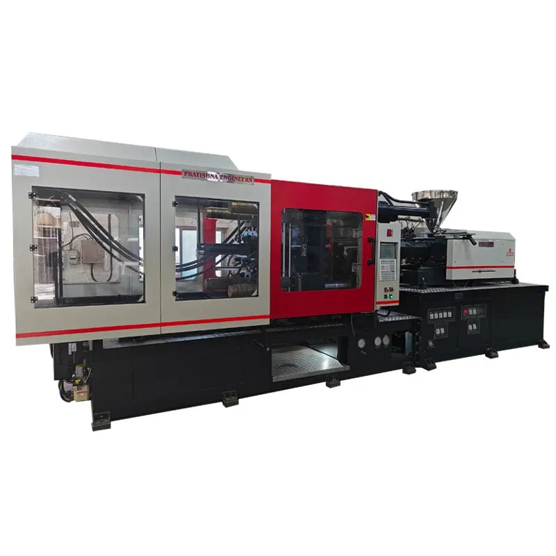

The role of injection molding machines in one moulding cycle
| Stage | What the machine does | What it controls |
|---|---|---|
| Clamp | Closes and locks the mould halves | Clamp force, close speed, mould protection |
| Inject | Screw pushes melt into the cavity | Injection speed, pressure, switchover point |
| Hold | Keeps pressure on while the part shrinks | Hold pressure and time until the gate freezes |
| Cool | Mould removes heat; screw recovers the next shot | Cooling time, screw speed, back pressure |
| Eject | Opens the mould and pushes the part out | Opening stroke, ejector stroke and force |
The role of injection molding machines is to turn plastic granules into finished parts in a repeating cycle: melt the resin, inject it into a closed mould, hold it under pressure, let it cool and push it out. The table above shows what the machine controls at each stage. The mould gives the part its shape and removes its heat, while the machine supplies force, melt, pressure and timing. Seen this way, a cycle problem may sit in the mould or the process window rather than in the headline tonnage.
Key Takeaways
- Each cycle runs clamp, inject, hold, cool and eject, and the machine controls force, speed, pressure and time at every one of those stages.
- Cooling time rises with the square of wall thickness, so the thickest wall of a part sets the cycle more than the speed of the machine.
- The mould shapes and cools the part, while dryers, chillers and part handling around the machine decide whether each cycle stays repeatable.
- Injection moulding suits solid three-dimensional parts made in volume; hollow bottles and continuous profiles belong to blow moulding and extrusion.
What does the machine do at each stage of the cycle?
The clamp closes and locks the mould, the screw injects melt at a set speed, hold pressure packs the part as it shrinks, the mould cools it while the screw prepares the next shot, and the ejectors push it out. Each stage has its own settings.
Clamping comes first. The moving platen closes fast, slows near the parting line so a trapped part cannot damage the mould, then builds the force needed to keep the halves shut against cavity pressure. Too little force gives flash; too much can crush vents, roll the parting line and crack cavity blocks.
Injection is a speed-controlled stage. The screw moves forward as a ram and fills most of the cavity, and the controller switches to hold at a set screw position or pressure. That switchover point decides whether the part fills cleanly or ends up short or flashed.
Hold pressure then packs extra melt in while the plastic shrinks, and it works only until the gate freezes. During cooling, the screw turns, melts the next shot and moves back against back pressure. Once the part is stiff enough, the clamp opens and the ejectors push it onto a chute, conveyor or robot gripper.
Why does cooling often set the cycle time?
Cooling often sets the cycle because heat has to travel through the plastic wall into the mould steel, and that takes time. Cooling time rises with the square of wall thickness, so the thickest section of a part sets the minimum cycle more than injection speed does.
In a trial on an eight-cavity ABS tensile bar 3.3 mm thick, RJG found that about 85% of the cycle was spent cooling. The part does not need to be cold to eject; only about 40% of the heat has to be removed before it is stiff enough to come out without distortion.
The square law is the useful part. A wall 20% thinner needs about 36% less cooling, because 0.8 × 0.8 = 0.64. A single thick boss or rib can therefore hold the whole part, and every cavity in the mould, to a longer cycle than the rest of the design needs.
When you calculate a cooling time, add about 20% as a safety factor, then confirm it on the shop floor. If parts warp or sink at the shorter time, look at mould cooling and part design before the machine. A machine cannot fix a badly cooled mould, however fast its clamp moves.
What is the role of injection molding machines in a moulding cell?
The machine is the centre of a cell that also includes the mould, a dryer or loader, a chiller and mould temperature controller, and part handling. It supplies force, melt and control, while the auxiliaries keep material, water and parts flowing so each cycle repeats.
Energy use shows how the work is shared. In a typical plant split published in an energy guide for moulders, polymer processing took 66% of energy, chillers 11%, compressed air 10% and water pumps 5%. The machine leads, but the cooling and air systems are large enough to need their own checks.
Material preparation matters as much. For one Indian PP homopolymer used for houseware and rigid packaging, the data sheet gives a melt range of 200 to 250 °C and a mould range of 20 to 50 °C. The machine must hold the barrel inside that window, and the chiller or controller must hold the mould inside its range.
Injection moulding fits solid three-dimensional parts made in volume, where the mould cost is spread over many parts: caps, housings, crates, gears and battery boxes. Hollow bottles come from blow moulding, often from injection moulded preforms, while pipes and profiles come from extrusion.
What should you note before you choose a machine?
Before you approach a supplier, note the thickest wall of the part, its projected area, shot weight, resin grade, mould height and the cycle time you need. These figures decide clamp force, barrel size, opening stroke and the auxiliaries around the machine. Browse the injection moulding machine range with them at hand.
Frequently Asked Questions About How Moulding Machines Work
What is the difference between the clamp unit and the injection unit?
The clamp unit opens, closes and locks the mould and resists cavity pressure. The injection unit holds the hopper, barrel, heaters and screw, and it melts, meters and injects the resin. The two are sized separately, so a machine can carry a larger or smaller barrel on the same clamp.
What is switchover in injection moulding?
Switchover is the point where the machine stops controlling injection by speed and starts controlling hold by pressure. It is usually set by screw position. Set too late, the cavity is overpacked and may flash; set too early, the part can come out short or with sink marks near thick sections.
Why does a moulded part need hold pressure?
Plastic shrinks as it cools, and hold pressure pushes in extra melt to make up for it. Hold works only while the gate is still open; once the gate freezes, more pressure does nothing. Hold pressure and time help control sink marks, voids and part weight from shot to shot.
Is injection moulding suitable for low volumes?
It can be, but the mould is a large fixed cost that has to be spread across the parts made. For a few hundred parts, simpler tooling or another process may cost less per part. As volumes rise, the low cost of each cycle on a moulding machine starts to win.
Do all resins need a dryer before moulding?
No. Resins such as PP and PE absorb very little moisture and usually run without drying. Hygroscopic resins such as nylon, PC and PET must be dried to the moisture limit on their data sheet, or the melt degrades and parts lose strength and surface quality.
Related Articles
- Plastic Injection Moulding Machines: Empowering Your Business for Growth
- The PHM Series Two Platen Injection Molding Machine: Revolutionizing Large Part Production
- Hybrid Injection Moulding Machines: Bridging Efficiency and Precision
- Vertical Locking Horizontal Injection Moulding Machine: A Synergy of Design and Efficiency
Sources & References
- RJG Inc.: How to Determine Injection Molding Cooling Time (Mar 2021)
- Plastics Technology, J. Williams (RJG): Clamp Tonnage: More Is Better...Right? (May 2017)
- ExxonMobil, AMI and Tangram Technology: An Energy Saving Guide for Injection Moulders
- Reliance Industries: Repol H110MAS Technical Data Sheet (July 2024)
Technical Disclaimer
Disclaimer: The information provided in this document is for general informational and educational purposes only. It is based on technical references and industry information available at the time of preparation and may be subject to change. It does not constitute engineering, technical, commercial or professional advice, nor does it constitute a quotation, specification, warranty or contractual commitment by Pratishna Engineers.
Actual injection moulding machine and process requirements vary according to the component design, material, mould, production volume, machine configuration and operating conditions. The information, examples, calculations and recommendations provided should be independently evaluated and verified for the specific application before making any equipment, process or production decision. Information obtained from third-party sources remains subject to the accuracy and limitations of those sources.
Limitation of Liability: Pratishna Engineers makes no representation or warranty, express or implied, regarding the completeness, accuracy or suitability of the information for any particular application. To the extent permitted by applicable law, Pratishna Engineers shall not be liable for any loss, damage, cost or consequence arising from reliance on or use of the information contained in this document. Final machine selection, configuration and application suitability should be confirmed with Pratishna Engineers based on complete and accurate project requirements.

