A batch of POM gears passes inspection on Monday and fails on Wednesday. Same mould, same resin lot, same setter. The difference is two seconds of packing time, trimmed to win back cycle. On a plastic gear moulding machine, that is a common story: gear size follows shrinkage, and shrinkage follows packing and cooling. Gears and connectors run well on a 120 t hybrid when those settings are held steady and the mould is gated for them.
This article covers what to control, how to gate and pack acetal, and what connectors add on top.
Key Takeaways
- LyondellBasell puts acetal shrinkage at 1.8% to 2.5% and nylon 66 at 0.7% to 1.8%, so small process changes move gear size.
- In a DuPont moulding trial on Delrin, 15 s of packing held the outside diameter to ±0.02 mm, while 5 s gave ±0.2 mm.
- Connectors add thin walls, fine pins and flame ratings that apply only at the wall thickness tested.
- Plugs and sockets made to IS 1293 must survive 10,000 insertions, so moulded dimensions affect test results, not only fit.
What Should a Plastic Gear Moulding Machine Control?
Packing pressure and time, melt temperature and cooling, the same way on every shot. These set how much the gear shrinks, and gear size follows shrinkage. An injection unit that repeats screw position, speed and pressure closely, as a servo-electric unit is built to, makes that control easier.
LyondellBasell's technical tip on mould shrinkage explains why gears are sensitive. PP, PE, nylon and acetal are semi-crystalline, and crystals shrink more than amorphous regions, which raises both shrinkage and its sensitivity to moulding conditions. Holding pressure reduces shrinkage only while the gate is still open.
DuPont's moulding tips for Delrin put numbers on it. Acetal is almost 60% crystalline. Its melt density is 1.17 g/cm³ against 1.42 for the solid, an 18% difference, made up of about 11% volume loss from crystallisation and 7% from cooling. Poor packing, DuPont notes, can cut mechanical performance by up to 30%.
DuPont trial on a Delrin part: packing and cooling against outside-diameter tolerance
| Settings | Outside diameter | Cycle |
|---|---|---|
| 15 s pack + 2 s cool | 49.61 ± 0.02 mm | 26 s |
| 15 s pack + 15 s cool | ± 0.07 mm | 41 s |
| 5 s pack | ± 0.2 mm | Not stated |
Two lessons follow. Short packing gave a tolerance ten times wider. And longer cooling in the mould did not tighten it; the shorter cooling time gave the better result in that trial.
How Do You Gate and Pack a POM Gear?
DuPont recommends a tunnel gate into the thickest section, with a gate diameter of at least half the wall and a land under 0.8 mm. Hold packing pressure until the gate area has frozen, then eject hot and let the gear cool on a conveyor before bulk packing.
The thickest section is usually the hub. Gating there lets packing pressure reach the section that shrinks most for as long as possible. A gate that is too small freezes early, and the hub then shrinks without being fed.
Temperature needs the same care. DuPont gives a recommended melt of 215 ± 5 °C, with nozzles and hot runners set to 190 °C, and warns that long residence or a high melt temperature degrades the resin. A barrel far larger than the shot adds residence time; the screw article in this series covers that check.
Our position: never trim packing time on a gear to save cycle. Find the gate freeze time by weighing parts at increasing pack times, set packing just beyond it, and look for cycle savings in cooling and mould opening instead.
What Makes Connectors and Switch Parts Different?
Thin walls, fine pins and latches, and flame-retardant grades. A connector must fill completely at its thinnest section every shot, and its flame rating applies only at the thickness the resin was tested at. Drying matters too, because PC and nylon grades pick up moisture from the air.
Covestro's data for Makrolon 6555, a flame-retardant PC, shows how thickness changes the rating: UL 94 V-0 at 3.0 mm but V-2 at 1.0 mm, and a glow-wire flammability index of 960 °C at 1.5 mm falling to 875 °C at 0.75 mm. A thinner connector wall can mean a lower rating.
The same datasheet asks for drying at 120 °C for 2 to 3 hours to a maximum moisture of 0.02%, a melt around 300 °C and a mould at 80 to 120 °C. Wet resin can look fine at the press and fail later, so dryer checks belong in the start-up routine.
DuPont adds a warning for shops that run both families: never process Delrin with PVC or flame-retardant resins, because the acids they release degrade acetal rapidly. Purge thoroughly before switching a machine from FR connectors to POM gears.
In India, the BIS blog on plugs, sockets and switches notes that IS 1293 and IS 3854 test mechanical strength with a pendulum hammer and run normal operation with the plug inserted and withdrawn 10,000 times. Contact positions and wall thickness that drift between shots can turn into test failures.
What Should You Send Before Moulding Gears or Connectors?
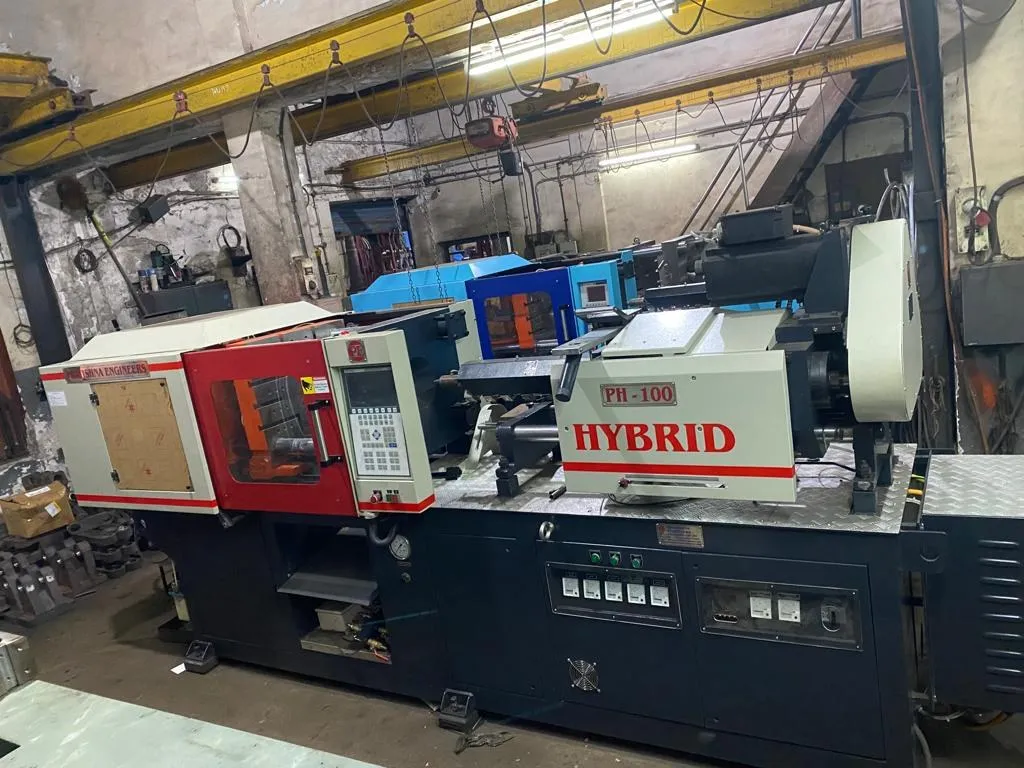
Send the gear or connector drawing with its critical dimensions and tolerances, the exact resin grade and flame rating needed, the wall thickness at the thinnest section, the cavity count and gate plan, and your monthly quantity. With those, shot, pressure and clamp can be checked first. See the 120 ton hybrid injection moulding machine page.
Frequently Asked Questions About a Plastic Gear Moulding Machine
Which plastic is used most for moulded gears?
Acetal (POM) and nylon are common choices because they combine stiffness, wear resistance and low friction. They behave differently in moulding: nylon must be dried carefully, and both are semi-crystalline with high shrinkage. Choose the resin for the gear's load, speed and environment, then size the machine and mould around it.
Can I run POM gears and FR connectors on the same machine?
Yes, with strict purging. DuPont warns never to process Delrin with PVC or flame-retardant resins, because the acids released can degrade acetal rapidly. Schedule the changeover, purge until the melt runs clean, and keep separate regrind bins so material cannot cross between the two jobs.
How many cavities should a precision gear mould have?
Start with the fewest cavities that meet your volume. Every extra cavity adds another chance of a slightly different fill, gate freeze or cooling rate, and gear tolerances leave little room for that. Prove one or two cavities first, then add more once the process holds size consistently.
Does a hybrid machine guarantee gear tolerance?
No. Repeatable injection removes one source of variation, but tolerance also depends on the mould steel, cooling layout, gate design, resin lot and drying. A well-built mould on a stable process does most of the work. Treat the machine as necessary for tight parts, but not sufficient on its own.
Why measure gears at a fixed time after moulding?
Semi-crystalline parts can keep changing size after ejection as they cool and settle. If one batch is measured hot and another the next morning, the numbers will not compare. Agree a conditioning time with your customer and measure every batch the same way, at the same temperature.
Related Articles
- What Can You Make on a 120 Ton Hybrid Injection Moulding Machine?
- 32 mm or 35 mm Screw on the PH 120: Pressure vs Shot Weight
- Power Consumption of a 120 Ton Hybrid vs Hydraulic Machine
Sources & References
- DuPont: Delrin Acetal Homopolymer Resin Molding Tips (DLE-A11169-00-B0615)
- LyondellBasell: Technical Tip: Mold Shrinkage
- Covestro: Makrolon 6555 product page
- Bureau of Indian Standards, N. Agarwal: Standards for Plugs-Socket-Outlets and Switches (February 2023)
Technical Disclaimer
Disclaimer: The information provided in this document is for general informational and educational purposes only. It is based on technical references and industry information available at the time of preparation and may be subject to change. It does not constitute engineering, technical, commercial or professional advice, nor does it constitute a quotation, specification, warranty or contractual commitment by Pratishna Engineers.
Actual injection moulding machine and process requirements vary according to the component design, material, mould, production volume, machine configuration and operating conditions. The information, examples, calculations and recommendations provided should be independently evaluated and verified for the specific application before making any equipment, process or production decision. Information obtained from third-party sources remains subject to the accuracy and limitations of those sources.
Limitation of Liability: Pratishna Engineers makes no representation or warranty, express or implied, regarding the completeness, accuracy or suitability of the information for any particular application. To the extent permitted by applicable law, Pratishna Engineers shall not be liable for any loss, damage, cost or consequence arising from reliance on or use of the information contained in this document. Final machine selection, configuration and application suitability should be confirmed with Pratishna Engineers based on complete and accurate project requirements.