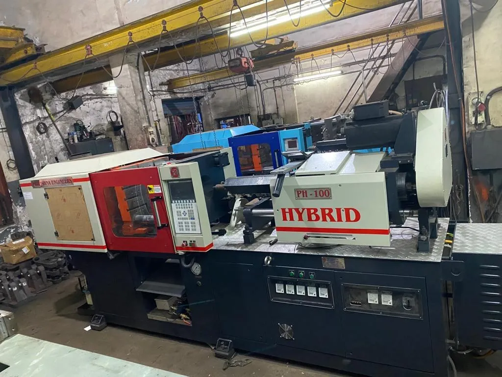
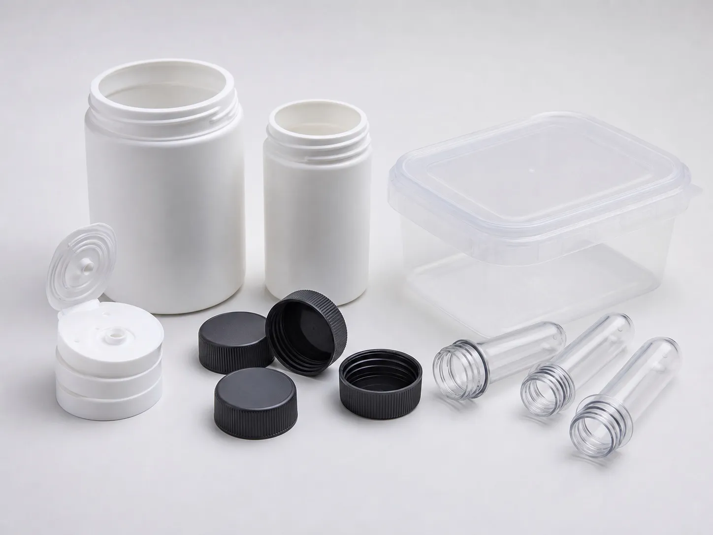
A new 16-cavity lid mould runs well for its first week. Then cavity 11 starts short-filling and cavity 3 shows a whisker of flash, while the other fourteen stay perfect. The machine has not changed. In multi cavity precision moulding, problems like this point to the mould first: runner balance, venting and cooling that differ by cavity. A 140 t hybrid runs such moulds well when four checks pass: clamp, shot, mould fit and balance.
This article takes each check in turn and ends with a worked 16-cavity example.
Key Takeaways
- Clamp is set by the total projected area of all cavities plus any cold runner; with a hot runner, only the cavities count.
- Vents, land widths and secondary vents should be identical cavity to cavity, and they can coin shut under repeated clamping.
- At minimum the cavities' projected area must sit inside the tie bars, because platens can pull in near them and wear the parting line.
- With a 10% reserve, 140 t can carry 16 cavities of a 45 mm PP lid at a tonnage factor of 3 US t/in².
What Limits Cavity Count in Multi Cavity Precision Moulding?
Four things: clamp across all cavities and the runner, shot size against the barrel, mould size against the tie bars, and how evenly cavities fill and cool. The lowest of the four sets the cavity count. On small parts, clamp may not be the first to run out.
The four limits on cavity count and how to check each
| Limit | How to check | What can run out first |
|---|---|---|
| Clamp | Area per cavity × cavities + cold runner, × tonnage factor, + reserve | Large-area parts and stiff resins |
| Shot | Shot volume + 10% inside 20% to 65% of swept volume | Heavy parts on a small barrel, tiny parts on a large one |
| Mould fit | Cavity layout and mould plates against tie bars, shut height, weight | Wide layouts and hot runner manifolds |
| Balance | Weigh each cavity's part; compare short shots | Long or unequal runners, vents, cooling |
Jeremy Williams of RJG gives the clamp method in Plastics Technology: projected area of one part, less through-holes, times cavities, plus the full cold-runner area, times a tonnage factor. With a hot runner, only the cavities count. On a 16-cavity mould, a cold runner can add a large share of the total.
Shot is the second filter. Sixteen small lids can add up to a modest shot, and a barrel sized for heavier work then runs them at a low share of its capacity, with long residence time. The worked example below shows the window for one layout.
Resin grade comes first for closures. Reliance lists its Relene 54GC016, a bimodal HDPE, for injection moulded caps and closures, with an MFR of 1.6 g/10 min, compliance with IS 10146 and IS 16738:2018, and a BIS designation under IS 7328. Its sister grade with slip additive, 54GC017, is listed for carbonated drink closures.
Why Do Some Cavities Fill Differently From Others?
Because each cavity sees a slightly different runner length, gate size, vent depth or coolant temperature. Small differences become big ones on thin or tight parts. A cavity that vents poorly traps gas, fills last and may short; one that vents too deep can flash.
Writing in MoldMaking Technology, Steve Shannon of The Estee Lauder Companies notes that vents, land widths and secondary vents must be identical cavity to cavity. Mould makers usually cut vents at the shallow end of the resin supplier's range, around 0.013 to 0.051 mm for PP, and the moulder tunes them.
His method suits multi-cavity tools. On a spare cavity and core stack, deepen vents in steps of about 0.005 to 0.008 mm, cycling after each, until whisker flash appears, then back off 0.005 mm. Repeated clamping can coin vents shut, so check both halves at each maintenance.
Cooling needs the same symmetry. Cavities at the edge of a large mould plate can run warmer or cooler than those in the middle if the water circuits differ, and their parts then shrink differently. Ask the mould maker for the circuit layout and measure water temperature at each return.
Our position: a 16-cavity mould running 14 good cavities is a 14-cavity mould with extra cost. Block the bad cavities, fix them at the next stop, and quote output on the cavities that work.
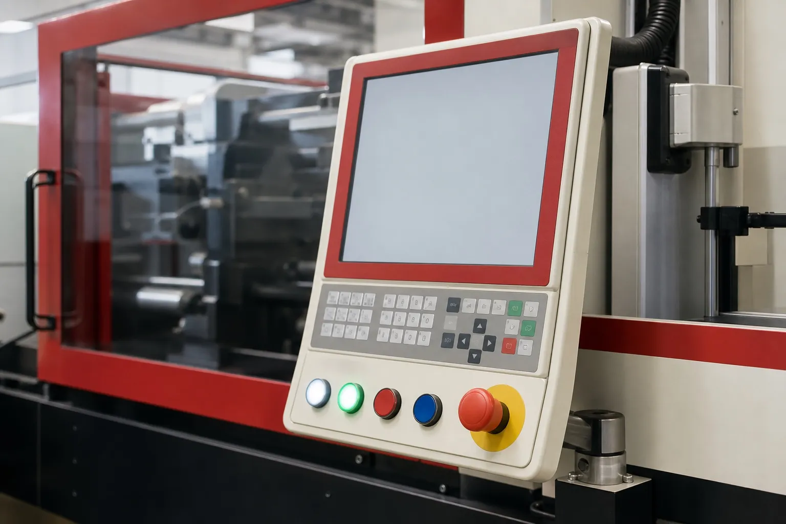
Repeatable injection does its part once the mould is right. An electric injection unit that repeats screw speed and position closely sends the same melt into the runner every shot, so any remaining differences stay where the mould puts them and are easier to trace.
Parts per hour by working cavities (12 s cycle, 98% good shots, calculated)
| Working cavities | Parts per hour | Parts per 8 h shift |
|---|---|---|
| 16 | 4,704 | 37,632 |
| 14 | 4,116 | 32,928 |
| 12 | 3,528 | 28,224 |
How Must a Multi-Cavity Mould Fit the Machine?
Ideally the whole mould sits within the tie bars, and at minimum the cavities' projected area must. Shut height must fall inside the machine's range, and mould weight inside its limit. Wide cavity layouts and hot runner manifolds can push a mould against these limits.
Brad Catoen sets out these checks in MoldMaking Technology. Platens can pull in near the tie bars and wear the parting line, so cavities near the edge suffer first. He also advises checking mounting and ejector patterns, noting that most moulds use a 101.6 mm or 120 mm locating ring.
He gives platen level and parallelism of 0.025 to 0.05 mm as generally acceptable for machines under 500 t. On a precision multi-cavity tool, poor parallelism shows up as flash on one side and short shots on the other.
Count hot runner zones too: nozzles plus manifold and sprue zones, plus spares. A controller with too few zones forces compromises on the very cavities you are trying to balance.
What Should You Send Before Planning Cavity Count?
Send the part drawing, resin grade, part weight, wall thickness, planned cavity count and layout, runner type, mould plate size and shut height, and target output. With those, clamp, shot and mould fit can be checked together. See the 140 ton hybrid injection moulding machine page.
Frequently Asked Questions About Multi Cavity Precision Moulding
Should a multi-cavity precision mould use a hot runner?
Often, because it removes runner area from the clamp calculation, cuts runner scrap and can improve balance. It also adds cost, zones to control and a heat source near every gate. For small runs or heat-sensitive resins, a well-balanced cold runner can be the simpler choice.
Can I block a cavity and keep production running?
Yes, if the mould is designed for it and the remaining cavities stay balanced. Blocking changes the flow through the runner, so recheck fill and packing on the cavities still running. Record which cavity is blocked and why, and fix it at the next planned stop.
How do I check balance across cavities?
Run a series of short shots at increasing fill and weigh or photograph each cavity's part. Cavities that fill last show where flow or venting differs. Then weigh full parts by cavity over several shots; a cavity that is consistently light or heavy needs attention in the mould.
Does a hybrid machine fix an unbalanced mould?
No. Repeatable injection keeps each shot the same, but it cannot make one cavity fill like another if the runner, gate, vent or cooling differs. Fix the mould first. The machine then holds the balanced condition steady from shot to shot and shift to shift.
How many temperature zones does a 16-cavity hot runner need?
One per nozzle, plus the manifold and sprue zones, plus a few spares. Sixteen nozzles, four manifold zones and one sprue give 21 zones; adding about 10% in spares takes the controller to 24. Confirm the zone count with the hot runner maker's drawing.
Related Articles
- What Can You Make on a 140 Ton Hybrid Injection Moulding Machine?
- PH 140 vs PH 120: When to Choose the Larger Hybrid
- Thin-Wall Filling at 220 MPa on a 140 Ton Hybrid Machine
Sources & References
- Plastics Technology, J. Williams (RJG): Clamp Tonnage: More Is Better...Right? (May 2017)
- MoldMaking Technology, S. Shannon: How to Determine the Proper Vent Depth (March 2019, updated December 2024)
- MoldMaking Technology, B. Catoen: Machine Sizing and Specification for Optimal Mold Performance, Part 1 (August 2025)
- Reliance Industries: Relene 54GC016 technical data sheet (February 2026)
Technical Disclaimer
Disclaimer: The information provided in this document is for general informational and educational purposes only. It is based on technical references and industry information available at the time of preparation and may be subject to change. It does not constitute engineering, technical, commercial or professional advice, nor does it constitute a quotation, specification, warranty or contractual commitment by Pratishna Engineers.
Actual injection moulding machine and process requirements vary according to the component design, material, mould, production volume, machine configuration and operating conditions. The information, examples, calculations and recommendations provided should be independently evaluated and verified for the specific application before making any equipment, process or production decision. Information obtained from third-party sources remains subject to the accuracy and limitations of those sources.
Limitation of Liability: Pratishna Engineers makes no representation or warranty, express or implied, regarding the completeness, accuracy or suitability of the information for any particular application. To the extent permitted by applicable law, Pratishna Engineers shall not be liable for any loss, damage, cost or consequence arising from reliance on or use of the information contained in this document. Final machine selection, configuration and application suitability should be confirmed with Pratishna Engineers based on complete and accurate project requirements.