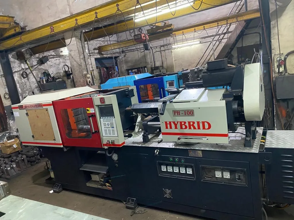

220 MPa is 2,200 bar, about 2,243 kg/cm² or about 31,900 psi. Thin wall injection moulding pressure typically runs above 30,000 psi, or about 2,068 bar, according to a PlasticsToday guide by Sabic's Greg Tremblay. So 220 MPa clears that line by about 6%. That is enough for small thin-walled parts on a 140 t hybrid, provided the clamp, fill speed, barrel size and mould are matched to the job.
Pressure is only one of five checks. This article covers all five and ends with a worked example for a PP tub.
Key Takeaways
- Thin-wall designs typically have flow length to wall ratios of 100:1 to 200:1 and need injection pressures above about 2,068 bar.
- Clamp rises to 5 to 8 US t/in², so with a 10% reserve a 140 t clamp holds about 113 to 181 cm² of thin-wall area.
- Fill speed matters as much as pressure: above 76 mm/s, often 152 mm/s, with fill times under 1 s.
- The shot should use at least 40% of the barrel; an oversized barrel weakens the pressure boost and adds residence time.
What Thin Wall Injection Moulding Pressure Do You Need?
It depends on the ratio of flow length to wall thickness, the resin's flow and the fill speed. Tremblay describes thin-wall designs as typically 100:1 to 200:1, needing pressures and speeds far above conventional moulding. Work out your ratio first; it tells you how hard the part is to fill.
Flow length to wall ratio for a 100 mm flow path (calculated)
| Wall thickness | Flow to wall ratio | Category |
|---|---|---|
| 1.0 mm | 100:1 | Lower end of thin-wall |
| 0.8 mm | 125:1 | Thin-wall |
| 0.6 mm | 167:1 | Thin-wall |
| 0.5 mm | 200:1 | Upper end of thin-wall |
Tremblay adds that resins for this work need high flow, low melt viscosity, and must tolerate shear heating of 50,000 s⁻¹ or more. Pushing a stiff resin through a thin wall with more pressure can cause anything from burning to flashing.
Remember where the pressure is measured. The machine's maximum is at the screw tip. The melt loses pressure through the nozzle, runner and gate before it reaches the far end of the cavity, so a part that needs close to the full figure at the screw has little reserve.
How Fast Must a Thin-Wall Part Fill?
Fast enough to fill before the thin melt front freezes. Tremblay gives injection velocities above 3 in/s, about 76 mm/s, with many jobs at 6 in/s, about 152 mm/s, and fill times under one second. Pressure without speed leaves short shots; speed without control leaves flash.
Control matters at those speeds. The guide lists the resolution a thin-wall machine should offer: about 1.0 mm/s for speed, 1 bar for pressure, about 0.1 mm for position, 0.01 s for time and 0.1 t for clamp.
This is where servo-electric injection earns its place. A ball screw driven by a servo motor follows a set speed and position profile closely from one shot to the next, which keeps fill time steady when the margin between full and short is a fraction of a second.
Our view: choose a high-flow resin before you chase more pressure. A grade designed for thin walls can fill at a lower pressure and speed, which leaves reserve for the day the resin lot or mould temperature drifts.
What Changes in the Clamp, Barrel and Mould?
Everything gets heavier. Tremblay puts thin-wall clamp at 5 to 8 US t/in², against 3 to 5 for conventional work, on machines that tend to have fast clamps and extra-thick platens. The barrel should be small enough for the shot to use 40% of it. Moulds need harder steel.
On platens, he notes that better thin-wall machines keep the ratio of tie-bar distance to platen thickness at 2:1 or less, and he advises against adapting conventional machines for this work. Ask for platen thickness and tie-bar spacing when you compare machines.
On barrels, he warns that too large a barrel may not give the pressure boost the part needs and allows the melt to degrade. On moulds, he recommends steels harder than P-20, as many support pillars as will fit, venting on core and ejector pins as well as the parting line, and larger cooling lines for more flow.
Ejection changes too. His rule of thumb is double the ejector pins, each twice as large, with blade or sleeve ejectors on ribs and bosses, because thin walls shrink little onto the core and can be hard to release.
Which PP Grades and Cooling Times Suit Thin Walls?
High-flow PP grades made for thin-walled containers, and cooling times that follow wall thickness squared. Thin walls cool quickly, which is much of the reason to design them, but only if the resin fills the part first. Choose the grade with the flow your ratio needs.
Reliance's Repol H200MA is an Indian example. Its datasheet lists a PP homopolymer with an MFR of 25 g/10 min for thin-walled containers, multi-cavity moulding and long flow paths, a melt range of 210 to 250 °C, and compliance with IS 10910 and IS 16738:2018 for food contact.
RJG explains that cooling time depends most on wall thickness, which is squared in the cooling equation, and suggests adding about 20% to the calculated cooling time as a safety factor. On that square law, a 0.5 mm wall needs about 69% of the cooling of a 0.6 mm wall.
What Should You Send for a Thin-Wall Trial?
Send the part drawing with wall thickness and the longest flow path from each gate, the resin grade, cavity count, runner type, shot weight, target cycle and any filling study. With those, pressure, speed, clamp and barrel can be checked together. See the 140 ton hybrid injection moulding machine page.
Frequently Asked Questions About Thin Wall Injection Moulding Pressure
Is the machine's maximum injection pressure the pressure in the cavity?
No. The rated figure is the pressure at the screw tip. Melt loses pressure through the nozzle, runner and gate, and again along the flow path, so the far end of the cavity sees much less. A filling study shows the pressure the part needs at the screw, which is the figure to compare.
Can any high-pressure machine mould thin-wall parts?
Pressure alone is not enough. Thin-wall work also needs high injection speed with fine control, a clamp that holds 5 to 8 US t/in² without platen bending, and a barrel the shot uses well. Check all of these, and the mould, before planning thin-wall production on any machine.
Why does a thin-wall shot need a smaller barrel?
Thin-wall shots are light for their area, so on a large barrel they use a small share of capacity. Tremblay recommends at least 40% for thin-wall work, since an oversized barrel may not deliver the pressure boost the part needs and keeps melt hot for longer, which can degrade it.
Do thin-wall parts need special moulds?
Usually, yes. Tremblay recommends steels harder than P-20, thicker plates, many support pillars, interlocks, venting on core and ejector pins, larger cooling lines and more generous ejection. A mould built for conventional walls can flex, flash or stick when run at thin-wall pressures and speeds.
Does a thinner wall always give a shorter cycle?
Cooling time falls with the square of wall thickness, so thinner walls cool much faster. But the part must fill first, which needs more pressure, speed and a higher-flow resin. If the thinner wall forces a slower, more careful fill or extra rejects, the overall cycle cost can rise instead.
Related Articles
- What Can You Make on a 140 Ton Hybrid Injection Moulding Machine?
- Multi-Cavity Precision Moulds on a 140 Ton Hybrid Machine
- PH 140 vs PH 120: When to Choose the Larger Hybrid
Sources & References
- PlasticsToday, G. Tremblay (Sabic Innovative Plastics): Never too thin (October 2007)
- Reliance Industries: Repol H200MA technical data sheet (July 2024)
- RJG Inc.: How to Determine Injection Molding Cooling Time (March 2021)
Technical Disclaimer
Disclaimer: The information provided in this document is for general informational and educational purposes only. It is based on technical references and industry information available at the time of preparation and may be subject to change. It does not constitute engineering, technical, commercial or professional advice, nor does it constitute a quotation, specification, warranty or contractual commitment by Pratishna Engineers.
Actual injection moulding machine and process requirements vary according to the component design, material, mould, production volume, machine configuration and operating conditions. The information, examples, calculations and recommendations provided should be independently evaluated and verified for the specific application before making any equipment, process or production decision. Information obtained from third-party sources remains subject to the accuracy and limitations of those sources.
Limitation of Liability: Pratishna Engineers makes no representation or warranty, express or implied, regarding the completeness, accuracy or suitability of the information for any particular application. To the extent permitted by applicable law, Pratishna Engineers shall not be liable for any loss, damage, cost or consequence arising from reliance on or use of the information contained in this document. Final machine selection, configuration and application suitability should be confirmed with Pratishna Engineers based on complete and accurate project requirements.