






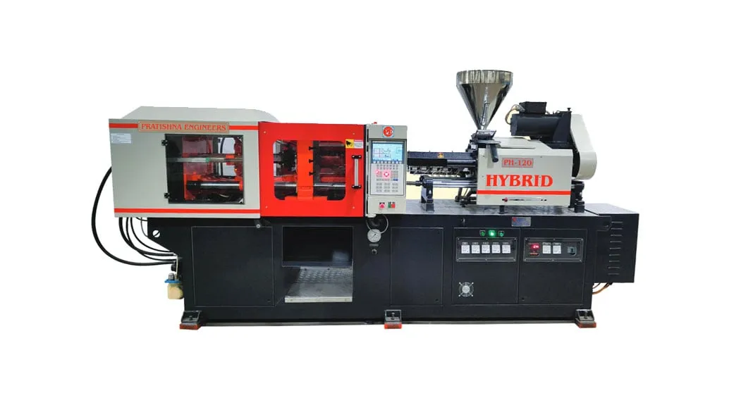

Automatic moulding machine manufacturers differ less in the machine itself than in what they integrate around it. The table shows the common levels of automation and what the manufacturer has to supply at each one, from a plain automatic cycle to a robot cell with insert loading and vision.
Levels of automation and what the manufacturer must supply
| Level | What happens each cycle | What the manufacturer supplies |
|---|---|---|
| Automatic cycle, gravity drop | The cycle repeats without an operator; parts fall onto a conveyor or into a bin | Reliable ejection, mould protection, guard interlocks |
| Sprue picker | An arm removes the sprue or runner | Picker mounting, signals and a runner chute |
| Take-out robot | Parts and runner are picked and placed on a conveyor or in trays | Robot interface, safety zone, platen or frame mounting |
| Robot cell with inserts and vision | Inserts are loaded and checked, parts removed and sorted | Interface, cell guarding, vision signals, process records |
Pratishna Engineers designs and builds injection moulding machines in Mumbai, and automation is part of the group's work alongside hydraulic systems and special purpose machines. This guide sets out the interface, safety, insert handling and after-sales questions to settle with any manufacturer, ours included, before you place an order.
Settle them early. Changing an interface or a guard after the machine is built costs time at commissioning, when production is already waiting.
Key Takeaways
- Agree the robot interface before ordering: EUROMAP 67 has long been the common hardware standard, and OPC 40079 has been published as its software-based successor.
- ISO 20430:2020 sets safety requirements for injection moulding machines; a robot cell also needs a guarded zone and interlocks agreed between both suppliers.
- For insert moulding, vision that confirms inserts are seated before the mould closes protects the mould and keeps bad parts inside the cell.
- In the worked example, a robot cell meets a 1,500 parts per shift target that manual removal misses, thanks to a 2 s shorter mould-open time.
Which Robot Interface Should an Automatic Machine Support?
Ask for EUROMAP 67, the long-standing standard interface between moulding machines and robots, and ask whether the controller is ready for OPC 40079, its software-based successor. Then confirm that your robot supplier supports the same interface, in writing, before either order is placed.
Plastics Technology reported that EUROMAP and the OPC Foundation worked together on OPC 40079, published first as a draft, as a software-based successor to the plug-and-cable EUROMAP 67 interface. For a buyer the point is compatibility: two interface types in one plant mean two sets of adaptors and skills.
Core machine and robot signals to see on the interface list
| Signal | Direction | Why it matters |
|---|---|---|
| Mould open complete | Machine to robot | Robot may enter the tool area |
| Robot clear of mould | Robot to machine | Machine may close |
| Ejector forward and back | Both ways | Part release timed with the gripper |
| Emergency stop | Both ways | One stop halts the whole cell |
Ask the manufacturer for the interface signal list and the wiring drawing. Mould open, mould closed, ejector forward and back, robot clear to close and emergency stop should all be listed, so the robot integrator can plan the cell before the machine reaches your floor.
Our position is firm: never accept a custom interface where a standard one will do. A standard plug lets you move a robot from one machine to another; a custom one ties the robot to a single machine for life.
If you plan production monitoring later, ask how process data leaves the controller and in what format.
What Safety Should Automatic Moulding Machine Manufacturers Build In?
The machine should meet ISO 20430:2020, the international safety standard for injection moulding machines, and the robot area needs its own guarding with interlocks tied into the machine. Agree who supplies and certifies each guard, because a cell has two suppliers and one set of hazards.
ISO describes 20430 as setting essential safety requirements for the design and construction of these machines, with information for safe use. It applies to machines with hydraulic or electrical drives for platen movement, and it does not apply to machines manufactured before its publication in 2020.
That last point matters when you automate an older machine. Adding a robot to a machine built before 2020 does not bring it under the standard, so the risk assessment for the whole cell has to be done fresh, by someone who signs for it.
Check the details on the trial: whether opening the robot fence stops the machine, whether the machine can close while the robot arm is inside the tool area, and how the operator resets the cell after a stop.
Ask for the safety documentation in the same pack as the electrical drawings.
How Do Inserts, Vision and Part Handling Change the Cell?
They make the mould-open time consistent and keep bad parts in the cell. A robot loading inserts and removing parts on the same path every cycle holds mould temperature steadier than a person can, and vision catches a missing or tilted insert before the mould closes.
A case study published through the Robotic Industries Association describes a four-cavity insert mould where unloading, cavity inspection and insert loading took 30 s by hand. A SCARA robot took over: it picked four parts and the runner, dropped the runner into a scrap chute and loaded inserts from a vibratory bowl feeder.
Vision did two jobs in that cell. Before moulding it confirmed the cavities were free of debris and the inserts were seated; after moulding it kept bad parts from leaving the cell. The report also notes that consistent mould-open times removed mould temperature fluctuations.
Our view: on an insert mould, a vision or sensor check of insert seating before the clamp closes is not an option to skip. One crushed insert can damage a cavity, and the repair takes far more downtime than the check ever will.
Plan the feeder, chute and part trays as part of the floor layout, not as add-ons.
What Support Should the Manufacturer Give After Commissioning?
Expect training for operators and maintenance staff on the machine and the cell, a documented interface and safety pack, spares for wear parts, and a clear split of responsibility between the machine maker and the robot integrator for every fault that can stop the cell.
The split matters most at night. When the robot waits for a signal the machine never sends, both suppliers can blame the other. Agree in the order who diagnoses interface faults, how fast each responds, and who keeps the signal list current after software changes.
Power is the other thing to plan. A robot, conveyor, feeder and chiller add load to the line. An MSEDCL grievance case quotes the utility's rule that if billing demand exceeds contract demand in a month, the load factor incentive is lost for that month, so add up the cell before you apply.
Finally, ask for the cell to be proven on your own mould at the manufacturer's works. A dry run without the real inserts and parts proves very little about the cycle you will get.
Keep a written record of the agreed cycle, reject rate and settings from that trial as the baseline for handover.
How Pratishna Engineers Supports Automated Moulding
Pratishna Engineers designs, manufactures, assembles and tests its machines in-house in Mumbai, where the facilities include CNC turning centres, vertical and horizontal machining centres, jig boring machines and assembly and testing bays. The design team works in SolidWorks, Creo and AutoCAD, and an independent QA department works to written SOPs.
The group, which includes Pratishna Technologies Private Limited, also builds special purpose machines, hydraulic systems and automation. Machine selection with customers follows a fixed order: component, material, mould, production requirement, then machine configuration. Automation is settled at the configuration step, once the part, mould and output target are known. That order keeps a robot from being specified before anyone knows how the part leaves the mould.
- A range across horizontal, vertical, vertical-horizontal combination, hydro-mechanical and hybrid machines, so the cell can be planned around the right clamp layout.
- 35+ years of machine building since 1991, with 9,000+ machines supplied to 1,000+ customers in India and international markets.
What Should You Share Before Planning an Automatic Cell?
Share the part drawing and material, the mould layout with cavities and inserts, the cycle and output target, how parts must be packed, and the robot or interface you already use. With that, the cell can be laid out and checked before the machine is built. See our injection moulding machines.
Frequently Asked Questions About Automatic Injection Moulding Machines
What is the difference between a sprue picker and a take-out robot?
A sprue picker is a simple arm that removes the sprue or runner each cycle, usually dropping it into a chute or granulator. A take-out robot handles the moulded parts themselves, placing them on a conveyor, in trays or at a downstream station. Many cells use one robot that handles both jobs.
Can a robot be added to an existing injection moulding machine?
Usually, if the controller offers a standard robot interface or can be upgraded to one, and there is room on the platen or a frame for the robot. Assess guarding for the whole cell, since a machine built before 2020 falls outside ISO 20430, and confirm ejection is reliable enough for robot pickup.
What is EUROMAP 67?
EUROMAP 67 is the long-standing standard electrical interface between an injection moulding machine and a handling robot. It defines the signals each side exchanges, such as mould open, robot clear and emergency stop, so robots and machines from different suppliers can work together without custom wiring.
Does a fully automatic cell still need an operator?
Yes, though not at the machine every cycle. Someone has to refill insert feeders and resin, change full boxes, respond to alarms, check parts against the quality plan and restart the cell after stops. One trained person can often look after several cells if they are laid out with that in mind.
Who is responsible for the safety of a robot cell?
Responsibility should be written into both purchase orders. The machine maker answers for the machine's own guarding, and the integrator answers for the robot zone and the interlocks between them. The plant owner remains responsible for the risk assessment of the complete cell and for keeping guards working.
Why is a consistent mould-open time important?
Mould temperature depends on how long the mould stays open between shots. When a person removes parts, the open time varies from cycle to cycle, and so does mould temperature. A robot opens and closes on the same timing every shot, which steadies cooling, shrinkage and part dimensions.
Related Articles
- Hydraulic Injection Moulding Machine Manufacturers: Meeting Your Plastic Molding Needs
- Vertical Injection Moulding Machine Manufacturers: An Overview
- Automatic Injection Moulding Machines in Mumbai: Smart, Fast and Reliable
- Why Automatic Injection Moulding Machines Are Perfect for Mass Production
Sources & References
- ISO: ISO 20430:2020 Plastics and rubber machines, Injection moulding machines, Safety requirements
- Plastics Technology: EUROMAP and OPC Foundation Collaborate on Industry 4.0 Compatible Standard
- Robotic Industries Association via Smart Molding, J. Clark: Automated injection molding operation
- MSEDCL: Case No. 17 of 2019 (contract demand and load factor incentive)
Technical Disclaimer
Disclaimer: The information provided in this document is for general informational and educational purposes only. It is based on technical references and industry information available at the time of preparation and may be subject to change. It does not constitute engineering, technical, commercial or professional advice, nor does it constitute a quotation, specification, warranty or contractual commitment by Pratishna Engineers.
Actual injection moulding machine and process requirements vary according to the component design, material, mould, production volume, machine configuration and operating conditions. The information, examples, calculations and recommendations provided should be independently evaluated and verified for the specific application before making any equipment, process or production decision. Information obtained from third-party sources remains subject to the accuracy and limitations of those sources.
Limitation of Liability: Pratishna Engineers makes no representation or warranty, express or implied, regarding the completeness, accuracy or suitability of the information for any particular application. To the extent permitted by applicable law, Pratishna Engineers shall not be liable for any loss, damage, cost or consequence arising from reliance on or use of the information contained in this document. Final machine selection, configuration and application suitability should be confirmed with Pratishna Engineers based on complete and accurate project requirements.

