






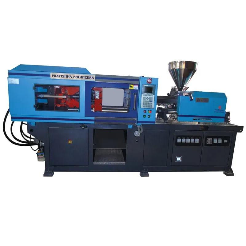

Horizontal injection moulding machine efficiency depends less on the press alone and more on the cell built around it. Before you add a machine or a robot, run through this five-point check:
1. Parts and runners leave the mould by gravity or by a picker, never by an operator reaching in.
2. A conveyor carries parts away, so the next shot never waits for a person.
3. The mould-open time is the same every cycle.
4. Mould changes follow a written routine with standard clamping and locating dimensions.
5. The machine is switched off, not left idling, during long stops.
Key Takeaways
- Measure efficiency as good parts per hour and energy per good part, not as machine speed alone, because a fast press in a slow cell gains nothing.
- A horizontal clamp lets parts fall clear of the mould, so a conveyor under the platens can replace manual collection on many jobs.
- A robot pays back mainly through a fixed mould-open time, which keeps mould temperature steady and the parts consistent from shot to shot.
- Mould change time is lost output, and standard locating rings, clamping patterns and preheated moulds can shorten it without buying another machine.
How do you measure horizontal injection moulding machine efficiency?
Measure it as good parts per hour and energy per good part. Output per hour equals 3,600 divided by the cycle in seconds, times cavities, times the share of good shots. Every second the cell adds to the cycle, and every rejected shot, comes straight off that figure.
The machine sets a floor for the cycle through its dry cycle, the time to close, lock, open and eject with no material. One mould-sizing guide puts it at 1 to 2.5 s for thin-wall machines and 3 to 5 s for others. Everything above that is moulding time or waiting time.
Cooling is usually the largest block. In one RJG trial on a 3.3 mm ABS part, about 85% of the cycle went on cooling, so mould water and wall thickness often matter more than injection speed. The layout cannot shorten cooling, but it can stop the mould sitting open after cooling ends.
Waiting time is where the layout shows. Watch a cell for one shift and log every cycle where the mould stayed open longer than set because a part stuck, an operator was away or a box was full. That log is your real baseline for efficiency.
Should parts drop by gravity, or does the cell need a robot and a conveyor?
Let parts drop by gravity when they can fall without scratching, tangling or landing in the wrong bin. Add a sprue picker when runners must be separated, and a robot when parts are cosmetic, need placing, carry inserts or must leave the mould in a fixed orientation.
Part removal options on a horizontal machine
| Removal method | Fits when | What the layout needs |
|---|---|---|
| Gravity drop | Sturdy parts that tolerate a fall; hot runner or runner-free moulds | Clear space under the platens and a chute or conveyor |
| Sprue picker | Cold runner moulds where runners go back to a granulator | Chute or granulator beside the machine |
| Robot with conveyor | Cosmetic parts, stacking, insert loading, fixed orientation | Guarded robot zone, conveyor and a defined mould-open signal |
| Operator removal | Low volumes, frequent changes, trial runs | Safe access through the gate; output varies with the person |
On a horizontal machine the mould opens sideways, so a part ejected off the core has a clear path down between the tie bars. That is a layout advantage a vertical clamp cannot give, and it costs nothing if the space under the platens is kept clear for a chute or belt.
A robot earns its place through repeatability more than speed. In a case study published by the Robotic Industries Association, consistent mould-open times removed mould temperature fluctuations, and vision checks kept bad parts inside the cell. When the open time changes with each operator, the mould runs hotter or colder from shot to shot.
A flat view from the shop floor: if a robot only replaces an operator's hands and still waits for a full bin to be changed, it is half used. Plan the conveyor, the box change and the reject path together with the robot.
How much floor space and mould change time should a horizontal cell plan for?
Plan floor space for the machine plus the robot zone, conveyor, dryer, chiller connections, mould trolley access and a clear gangway. Plan mould change time as lost output and cut it with standard locating rings, matching clamp patterns, pre-set water circuits and moulds brought to temperature beforehand.
A horizontal machine is long, and the floor it needs is set by the mould change route as much as by the frame. If the crane or trolley cannot reach the platens without moving another machine, every change takes longer than the work itself.
Mould fit decides the routine. A sizing guide in MoldMaking Technology notes that most moulds use a 101.6 mm or 120 mm locating ring, and that a mismatch in mounting or ejector patterns may need an ejector box. Standardise these across your moulds and machines, and changes become repeatable.
Idle time is the other hidden loss. Measurements reported in PlasticsToday found idling machines drawing 52% to 97.5% of their full moulding energy. In Maharashtra this shows up on the bill, because MSEDCL charges energy in kVAh and demand in kVA, so idling motors at a low power factor are paid for twice.
What should you map before planning your next horizontal cell?
Map one week of a running cell first: cycle time, open-mould waiting, rejects, mould changes and idle hours. Then decide whether the next gain comes from a conveyor, a robot, a change routine or a larger machine. For machine options and layouts, see the horizontal injection moulding machine range.
Frequently Asked Questions About Horizontal Moulding Cell Efficiency
Do all horizontal machines need a conveyor under the mould?
No. A conveyor helps when parts drop by gravity and the machine runs unattended, because it moves each shot clear before the next one lands. Low-volume jobs with frequent changes can run without one, but someone must then empty the bin before it overflows and stops the cycle.
How long should a mould change take?
There is no single figure; it depends on mould size, water circuits, hot runner zones and crane access. Time your current changes for a month, then target the slowest steps first. Standard locating rings, matching clamp patterns and preheated moulds often give a large cut without new equipment.
Is it cheaper to switch off a machine during a long stop?
Often, yes. Idling machines can draw more than half of their full moulding energy, and stops longer than about 1.5 hours may be cheaper to switch off and restart. A clamp-meter logger can measure your machine in as little as 30 minutes, so check before you set the rule.
Why does a robot improve part consistency?
A robot picks on the same timing every cycle, so the mould stays open for the same time and holds a steady temperature. Manual removal varies with the person and the shift, and that variation shows up as changes in shrinkage, dimensions and surface finish from one shot to the next.
How does power factor affect a moulding unit's electricity bill in Maharashtra?
MSEDCL bills HT and larger LT consumers on kVAh for energy and kVA for demand, so a poor power factor raises both. Its own FAQ notes that at 0.85 power factor, 15% of the power drawn does no useful work. Capacitor banks or an APFC panel are the usual fix.
Related Articles
- Applications of Two-Platen Injection Moulding Machines in Large-Scale Projects
- Applications of PV Series Plastic Injection Moulding Machines in Consumer Electronics
- Horizontal Injection Moulding Machines: Maximizing Production Efficiency
- The Role of Toggle Moulding Machines in High-Precision Manufacturing
Sources & References
- Robotic Industries Association via Smart Molding, J. Clark: Automated injection molding operation
- PlasticsToday, R. Kent: Getting to know your real energy use and cost (Jan 2010)
- MoldMaking Technology, B. Catoen: Machine Sizing and Specification for Optimal Mold Performance, Part 1 (Aug 2025)
- MSEDCL: kVAh Billing: Frequently Asked Questions
Technical Disclaimer
Disclaimer: The information provided in this document is for general informational and educational purposes only. It is based on technical references and industry information available at the time of preparation and may be subject to change. It does not constitute engineering, technical, commercial or professional advice, nor does it constitute a quotation, specification, warranty or contractual commitment by Pratishna Engineers.
Actual injection moulding machine and process requirements vary according to the component design, material, mould, production volume, machine configuration and operating conditions. The information, examples, calculations and recommendations provided should be independently evaluated and verified for the specific application before making any equipment, process or production decision. Information obtained from third-party sources remains subject to the accuracy and limitations of those sources.
Limitation of Liability: Pratishna Engineers makes no representation or warranty, express or implied, regarding the completeness, accuracy or suitability of the information for any particular application. To the extent permitted by applicable law, Pratishna Engineers shall not be liable for any loss, damage, cost or consequence arising from reliance on or use of the information contained in this document. Final machine selection, configuration and application suitability should be confirmed with Pratishna Engineers based on complete and accurate project requirements.

