







PV series vertical moulding machine applications at a glance
| Application | Why vertical injection with a horizontal clamp helps | Points to check |
|---|---|---|
| Cable plugs and cord strain reliefs | The cable lies along the parting line while the nozzle injects from above | Cable grip in the mould, melt temperature for PVC or TPE |
| Connectors and terminal blocks with metal pins | Pins are located on core pins or in pockets before the mould closes | Pin location, flash on contact faces, insert supply |
| Charger and adaptor housings with brass inserts | Threaded inserts are moulded in for repeated assembly | Boss size, hoop stress, insert preheating |
| Small switch and socket parts | Small shots on a 40 t or 55 t clamp | Material grade for heat and fire tests |
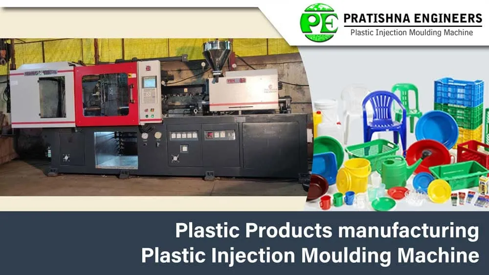
Pratishna Engineers' PV series is a vertical injection, horizontal clamp machine built in 40 t and 55 t sizes. Its main uses are insert and cable moulding: plug tops, cord strain reliefs, connectors with metal pins and small housings with threaded inserts, the kind of parts found in chargers, adaptors and other consumer electronics accessories. The nozzle comes down from above into the parting line, so a cable or wire can run out of the mould along the split. That makes PV series vertical moulding machine applications strongest where a metal or cable part must be overmoulded with a small, controlled shot. If your part is plain plastic with no insert, a standard horizontal machine is often the simpler choice.
Key Takeaways
- The PV series injects vertically into a horizontally clamped mould, which suits cables and wires that must leave the mould along the parting line.
- Typical uses are plug tops, strain reliefs, pin connectors and small housings with moulded-in brass inserts, all on shots within the series sheet limits.
- Insert parts need attention to insert location, boss size, preheating and hoop stress, which decide whether parts crack weeks after they are moulded.
- Plugs, switches and enclosures sold in India fall under BIS standards and quality control orders, so material and moulding records matter as much as cycle time.
Which parts suit PV series vertical moulding machine applications?
Small parts that carry a cable, wire or metal insert suit it best: plug tops, cord strain reliefs, pin connectors, sensor heads and small housings with threaded inserts. The vertical nozzle feeds the parting line, leaving the clamp direction free for cables and inserts.
Shot size sets the upper limit. The PV 40 has a maximum shot of 64 g of PS and the PV 55 130 g of PS, so the series is aimed at small overmoulded parts rather than large housings. PVC is denser than PS: a GEON guide notes that a barrel rated 80 oz of PS holds about 105 oz of PVC.
Cable overmoulding is the clearest case. The cable is laid in a groove in the mould, the mould closes and grips it, and melt fills the plug or strain relief around it. Because the melt enters at the parting line from above, the runner sits on the split and both mould halves stay free for cable grooves and insert pockets.
Connectors with metal pins follow the same logic. Pins are placed on core pins or in pockets before the mould closes, and the melt flows around them. Flash on a contact face is a reject, so pin location and the fit of the shut-off around each pin matter more than injection speed.
How should insert moulding be set up for cable and electrical parts?
Locate each insert positively on a pin or pocket, preheat it, give it rounded knurling for grip, and size the boss around it. Then test finished parts with temperature cycling, because cracks from hoop stress often appear after moulding rather than at the machine.
Design guidance summarised by PlasticsToday from DuPont gives practical limits: inserts should protrude at least 0.4 mm into the cavity, the plastic beneath should be at least one sixth of the insert diameter, and the boss should be about 1.5 times the insert diameter for inserts up to 12.9 mm.
Hoop stress can be screened before tooling. Multiply the resin's mould shrinkage by its flexural modulus. The same source estimates acetal at about 52.4 MPa, roughly 75% of its tensile strength, which explains why rigid, high-shrink grades crack around metal and toughened grades are preferred.
Moulded-in inserts give the best pull-out and torque because they are fully encapsulated, but they need close tolerance between the insert and its locating pin and take time to place. Brass is the most common insert material. If the part allows it, heat staking after moulding can be the faster route for thermoplastics.
Which Indian standards apply to moulded plugs, switches and enclosures?
Switches to IS 3854 are under compulsory BIS certification, boxes and enclosures to IS 14772 came under the Electrical Accessories Quality Control Order, 2023, and plugs and sockets are tested to IS 1293. The moulded part must pass heat, fire and mechanical tests.
A BIS article on IS 1293 and IS 3854 lists what the tests cover: earthing, protection against shock, dimensions, resistance to abnormal heat and fire, mechanical strength by pendulum hammer, and normal operation with a plug inserted and withdrawn 10,000 times. Each of these depends on the moulded material and on consistent moulding.
The 2023 order, dated 1 January 2024, also covers cable trunking, lamp holders and switch-socket-outlets, with longer compliance periods for small and micro enterprises and an exclusion for goods made for export. For a moulder supplying these products in India, customers may ask for resin certificates and batch records along with the parts.
Cords add one more test. IEC 60884-1, the international standard for plugs and sockets, includes a cord anchorage test of 100 pulls of 60 N, one each second. An overmoulded strain relief has to grip the cable well enough to pass it, which depends on material bonding and the mould shut-off around the cable.
How do you check a part against the PV 40 and PV 55 figures?
Check four things in order: clamp force against projected area, shot weight against the part plus runner, mould size against tie-bar space and thickness, and opening stroke against part height. The table gives each figure as published on the series sheet.
PV series figures (from the series sheet)
| Item | PV 40 | PV 55 |
|---|---|---|
| Mould clamping force (t) | 40 | 55 |
| Screw diameter (mm) | 27 | 35 |
| Max. shot weight (g, PS) | 64 | 130 |
| Max. injection pressure (kg/cm²) | 1,300 | 1,065 |
| Mould clamping stroke (mm) | 200 | 225 |
| Mould thickness, min to max (mm) | 125 to 300 | 125 to 300 |
| Max. daylight opening (mm) | 500 | 525 |
| Space between tie bars, H x V (mm) | 265 x 195 | 350 x 298 |
| Platen size (mm) | 415 x 370 | 480 x 415 |
| Ejector stroke (mm) / ejector force (t) | 40 / 1.7 | 50 / 2.0 |
| Electric motor / heating capacity (HP) | 5 / 3.5 | 7.5 / 5 |
| Floor space, L x W x H (m) | 1.85 x 0.75 x 2.5 | 2.3 x 0.9 x 2.5 |
Read the clamp first. With a 10% reserve, a starting margin and not a rule, 40 t holds a part area of roughly 86 to 129 cm² at 2 to 3 US tons per square inch, and 55 t about 118 to 178 cm². That covers several plug-top cavities but not a large housing.
Then check the mould. It must be 125 to 300 mm thick and should fit between the tie bars. A rule of thumb from Plastics Technology is that the mould covers at least 70% of the tie-bar gap, which means about 186 x 137 mm on the PV 40 and 245 x 209 mm on the PV 55.
Finally, the opening. A part needs the mould to open about 2.5 times its height, so a 200 mm stroke suits parts up to about 80 mm tall and a 225 mm stroke about 90 mm. Check your tallest part, including any cable exit, against these limits.
How Pratishna Engineers builds and supports the PV series
Pratishna Engineers was founded in Mumbai in 1991 by Nandkumar R. Kushe, a first-generation engineer, and has 35+ years of experience, with 9,000+ machines and 1,000+ customers in India and international markets. Design, manufacturing, assembly, testing and service are done in-house at its Mumbai facilities of about 25,000 sq ft.
The vertical range covers the PV series, with a horizontal clamp and vertical injection, and the PVDL series, with a vertical clamp and vertical injection. Machine selection with each customer follows a fixed order: component, material, mould, production requirement, then machine configuration. For a PV application, that means the cable or insert and the mould are settled before the model.
- Machine shop with CNC turning centres, vertical and horizontal machining centres and jig boring machines, plus assembly and testing facilities.
- Design in SolidWorks, Creo and AutoCAD, with an independent QA department working to written SOPs.
What should you send to check a part on the PV series?
Send the part drawing, the cable or insert details, the resin grade, the cavity count and the monthly volume. With those, clamp, shot, mould size and opening can each be checked before a trial. See the PV series vertical injection moulding machine page for the full specification.
Frequently Asked Questions About PV Series Applications
What is the difference between the PV and PVDL series?
The PV series closes the mould horizontally and injects vertically from above. The PVDL series both closes and injects vertically, which suits loose inserts that can rest in a horizontal lower mould half. Choose PV when a cable or wire needs to leave the mould along a vertical parting line.
What does PVC overmoulding need from the machine?
PVC is heat and shear sensitive, so it needs a streamlined melt path with no dead spots, a suitable screw and barrel metal, and care never to leave it sitting hot in the barrel. A GEON moulding guide also warns that PVC and acetal must never meet at processing temperature.
Why do moulded-in brass inserts crack later?
The plastic shrinks onto the metal as it cools and keeps a hoop stress around the insert. In rigid, high-shrink grades that stress can be a large share of the material strength, so cracks appear days or weeks later. Preheated inserts, rounded knurls, adequate boss walls and toughened grades reduce the risk.
Does an overmoulded strain relief need to pass a pull test?
Plugs made to IEC 60884-1 go through a cord anchorage test of 100 pulls of 60 N on the cord, followed by a torque test. Check which standard your customer's product follows and test sample plugs early, because grip depends on material bonding and on how the mould closes around the cable.
How many cavities can a 40 t clamp run for small connectors?
Divide the usable clamp by the clamp each cavity needs. With a 10% reserve and 2 to 3 US tons per square inch, 40 t holds about 86 to 129 cm² of projected area, runner included. Small connectors of a few square centimetres each leave room for several cavities, subject to shot size.
Who designs and builds the PV series?
The PV series is designed and built by Pratishna Engineers in Mumbai, where design, manufacturing, assembly, testing and service are done in-house. The company was founded in 1991 and has 35+ years of experience, with 9,000+ machines and 1,000+ customers in India and international markets.
Is the PV series suited to consumer electronics parts?
It suits the small insert and cable parts used in chargers, adaptors, cords and connectors, within its shot limits of 64 g and 130 g of PS. Large covers or housings with no insert are better made on a horizontal machine sized for their projected area and shot weight.
Related Articles
- How Horizontal Injection Moulding Machines Boost Efficiency in Manufacturing
- Applications of Two-Platen Injection Moulding Machines in Large-Scale Projects
- The Benefits of Vertical Injection Moulding Machines for Compact Spaces
- Vertical Injection Moulding Machines: Innovating Manufacturing
Sources & References
- PlasticsToday (IMM), summarising A. Miller, DuPont: Design and material advice from the pros, Part 3: Insert molding essentials (Sept 2005)
- BIS Blog, N. Agarwal: Standards for Plugs-Socket-Outlets and Switches (Feb 2023)
- Gazette of India (DPIIT): Electrical Accessories (Quality Control) Order, 2023
- GEON Performance Solutions: Injection Molding Guide: GEON PVC Molding Formulations (PG0019BC, 2021)
Technical Disclaimer
Disclaimer: The information provided in this document is for general informational and educational purposes only. It is based on technical references and industry information available at the time of preparation and may be subject to change. It does not constitute engineering, technical, commercial or professional advice, nor does it constitute a quotation, specification, warranty or contractual commitment by Pratishna Engineers.
Actual injection moulding machine and process requirements vary according to the component design, material, mould, production volume, machine configuration and operating conditions. The information, examples, calculations and recommendations provided should be independently evaluated and verified for the specific application before making any equipment, process or production decision. Information obtained from third-party sources remains subject to the accuracy and limitations of those sources.
Limitation of Liability: Pratishna Engineers makes no representation or warranty, express or implied, regarding the completeness, accuracy or suitability of the information for any particular application. To the extent permitted by applicable law, Pratishna Engineers shall not be liable for any loss, damage, cost or consequence arising from reliance on or use of the information contained in this document. Final machine selection, configuration and application suitability should be confirmed with Pratishna Engineers based on complete and accurate project requirements.

