






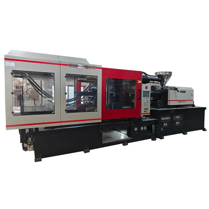

A PHM series two platen injection molding machine clamps the mould between a fixed platen and a moving platen, with no toggle linkage or rear platen, so it gives a long opening stroke in a shorter frame. Pratishna Engineers builds the PHM series in four sizes from 160 t to 350 t, with clamp strokes of 1,000 mm to 1,350 mm and maximum daylight of 1,225 mm to 1,650 mm.
The figures that decide a large job are rarely the tonnage. They are the usable opening at your mould height, the tie-bar space your mould must sit inside, and the shot your resin needs. This overview walks through each one and shows how to check it against a tall or wide part.
Key Takeaways
- On a two-platen clamp the usable opening shrinks as mould height rises, so compare opening at your mould height, not the headline stroke.
- PHM daylight equals minimum mould thickness plus full stroke, from 1,225 mm on the 160 t model to 1,650 mm on the 350 t model.
- Size tonnage from projected area and a tonnage factor; PP commonly sits at 2 to 3 US tons per square inch of projected area.
- Connected load runs from 38.6 kW to 81 kW across the series, so check contract demand and power factor before installation.
How is the PHM series two platen injection molding machine built?
It uses a fixed platen and a moving platen, with no rear toggle platen. On hydro-mechanical clamps of this kind, the moving platen travels quickly to close, is locked mechanically, and short cylinders then build tonnage. The series sheet lists the PHM as hydro-mechanical, from 160 t to 350 t.
Removing the toggle linkage and its rear platen shortens the machine for a given stroke. Industry reports on two-platen hydro-mechanical clamps also point to a wider range of mould heights and finer control of clamp pressure, while toggles are reported to lock slightly faster and give more opening force for deep-draw parts.
The trade-off is real, not a sales line. A toggle wins on simple, fast, repetitive work in moderate moulds. A two-platen clamp earns its place when moulds are tall, heavy or changed often, and when frame length matters on a crowded shop floor. On a large mould changed every shift, easier access around the clamp often matters more than a fraction of a second at lock-up.
Two-platen and toggle clamps compared, as reported in industry literature
| Point | Two-platen clamp | Toggle clamp |
|---|---|---|
| Machine length | Shorter for a given stroke | Longer, with a rear platen and linkage |
| Opening vs mould height | Usable opening falls as mould height rises | Full stroke at every mould height |
| Lock-up speed | Reported slightly slower | Reported slightly faster |
| Opening force | Reported lower | Reported higher, suits deep-draw parts |
| Clamp pressure control | Reported finer and more uniform | Reported harder to run below maximum tonnage |
| Wear points | Fewer moving links | Parallelism risk if links wear unevenly |
How do stroke, mould thickness and daylight work together?
On a two-platen clamp, daylight is fixed and the mould uses part of it. Usable opening equals daylight minus mould height, so the full stroke appears only at the minimum mould thickness. On the 160 t model, 225 mm plus 1,000 mm gives 1,225 mm.
That relationship turns the headline stroke into a range. At its 645 mm maximum mould thickness, the 160 t model opens 580 mm. The 200 t model opens 685 mm at 655 mm, the 250 t model 700 mm at 700 mm, and the 350 t model 850 mm at 800 mm.
A toggle behaves differently: its maximum daylight equals maximum shut height plus stroke, so the full stroke is available at every mould height. When your mould is tall, compare the usable opening of each option at that height rather than comparing strokes on paper.
A common guide for clean part removal is an opening of at least 2.5 times the part height. A 250 mm deep crate therefore wants 625 mm of usable opening, a figure that rules out some moulds that would clamp comfortably on tonnage alone.
Which PHM figures should you check against your mould and part?
Check five figures in order: tie-bar space, mould thickness range, usable opening, shot volume in your resin, and ejector stroke. Tonnage comes last as a confirmation, because a large part usually fails on fit or opening before it fails on clamp force.
Tie bars run from 460 x 440 mm on the 160 t model to 720 x 720 mm on the 350 t model. Ideally the whole mould sits inside that space; at minimum every cavity must, because platens can pull in near the tie bars and wear the parting line.
Shot ratings are in grams of polystyrene. Working in volume with melt densities of about 0.945 g/cm³ for PS and 0.74 g/cm³ for PP, plus 10% for leakage, a good PP shot sits between roughly 14% and 46% of the PS rating. On the 1,492 g barrel of the 350 t model, that is about 212 to 691 g of PP.
Ejector stroke is 150 mm on the 160 t model, 200 mm on the 200 t and 250 t models, and 250 mm on the 350 t model. Deep parts with shallow draft need that stroke, or a release system built into the mould. Platen size matters too: heavy moulds need their weight checked for both platens, not only the moving one, and the mould base must leave room for clamps or bolts.
PHM series figures as printed on the series sheet
| Figure | PHM-160 | PHM-200 | PHM-250 | PHM-350 |
|---|---|---|---|---|
| Mould clamping force (t) | 160 | 200 | 250 | 350 |
| Mould clamping stroke (mm) | 1,000 | 1,100 | 1,150 | 1,350 |
| Mould thickness, min to max (mm) | 225 to 645 | 240 to 655 | 250 to 700 | 300 to 800 |
| Max. daylight opening (mm) | 1,225 | 1,340 | 1,400 | 1,650 |
| Tie-bar space, H x V (mm) | 460 x 440 | 560 x 540 | 640 x 640 | 720 x 720 |
| Platen size (mm) | 800 x 815 | 935 x 960 | 1080 x 1128 | 1195 x 1250 |
| Screw diameter, A / B (mm) | 45 / 50 | 55 / 60 | 65 / 70 | 75 / 80 |
| Max. shot weight PS, A / B (g) | 343 / 424 | 588 / 700 | 836 / 969 | 1311 / 1492 |
| Ejector stroke (mm) / force (t) | 150 / 7.5 | 200 / 7.5 | 200 / 9.5 | 250 / 12 |
| Total connected load (kW) | 38.6 | 50.6 | 62.2 | 81 |
What do the connected load figures mean for your power supply?
They size your supply, not your bill. Total connected load is 38.6 kW on the 160 t model and 81 kW on the 350 t model, split between a servo-driven pump and barrel heating. Actual draw during moulding is lower and depends on the cycle, the mould and idle time.
In Maharashtra, MSEDCL bills energy in kVAh and demand in kVA for HT consumers and for LT consumers above 20 kW. At a power factor of 0.85, 15% of the power drawn does no useful work, so plan capacitors or an APFC panel before a large machine is added to the line.
The pump on these models is servo driven, listed at 24.1 kW to 48.2 kW. A servo pump slows when the circuit needs no oil, which cuts the load during cooling and hold compared with a fixed-speed pump. Heaters, listed at 14.5 kW to 32.8 kW, still draw power whenever the barrel is hot.
Check the contract demand on your current bill before you order. A new 50 kW to 80 kW machine on an existing connection can push maximum demand over the sanctioned figure, and that problem is cheaper to solve on paper than after installation. A power analyser log over a few typical cycles on your existing machines gives a better base figure than any nameplate.
How Pratishna Engineers builds and backs the PHM series
The PHM series belongs to a range that Pratishna Engineers has developed in Mumbai since 1991, covering horizontal, vertical, PET, hybrid and two-platen machines as well as special-purpose builds. The company began with machine rebuilding, indigenisation and technology adaptation, and import substitution remains a stated focus.
The Mumbai facilities, about 25,000 sq ft, include CNC turning centres, vertical and horizontal machining centres, jig boring machines and precision conventional machine tools, with assembly and testing facilities alongside. Large platens and frames are therefore machined, assembled and tested under one roof. The design team works in SolidWorks, Creo and AutoCAD, which lets a large mould be checked against platen, tie-bar and ejector layouts on screen before a machine is committed.
- 35+ years of experience, 9,000+ machines and 1,000+ customers in India and international markets.
- An independent QA department works to written SOPs, with accredited external labs used when required.
What should you send before shortlisting a two-platen machine?
Send the mould drawing with its height, width and weight, the part height, the projected area per cavity, the resin grade and shot weight, and your target cycle. With those, usable opening, fit and clamp can be checked together. See the two-platen injection moulding machine page.
Frequently Asked Questions About the PHM Series
What is the difference between a two-platen and a toggle machine?
A toggle uses a linkage and a rear platen to multiply cylinder force and lock the mould. A two-platen clamp locks the moving platen directly and builds tonnage with short cylinders. The two-platen frame is shorter, but its usable opening falls as mould height rises, so check opening at your height.
Why does usable opening change with mould height on a PHM machine?
Daylight is the fixed maximum gap between the platens. A taller mould takes more of it and leaves less for opening. On the 250 t model, a 250 mm mould leaves the full 1,150 mm stroke, while a 700 mm mould leaves 700 mm. Always calculate opening at your actual mould height.
How do I convert the PS shot rating to PP?
Work in volume. Divide the PS rating by about 0.945 g/cm³ to get swept volume, multiply by about 0.74 g/cm³ for PP melt, then keep the shot between roughly 20% and 65% of that figure after a 10% allowance. The result is about 14% to 46% of the PS rating.
Can a two-platen machine run a mould smaller than the tie-bar space?
Yes, within limits. The mould must be at least as thick as the minimum shut height, which is 225 mm to 300 mm across the PHM sizes, and every cavity must sit inside the tie bars. Very small moulds on large platens need checking against the minimum mould size in the machine manual.
Is a two-platen machine more energy efficient than a toggle?
Not by clamp type alone. Energy use depends mostly on the pump drive, heater losses, idle time and whether the machine is sized to the job. A servo-driven pump, as listed on the PHM sheet, slows when no oil is needed, which matters more than the clamp layout.
How does Pratishna Engineers select a PHM model for a job?
Selection runs in a fixed order: component, material, mould, production requirement, then machine configuration. For a PHM enquiry that means the part drawing and resin first, then mould height, width and weight, then volume and cycle, before a model and screw size are proposed for your application.
Related Articles
- PV Series Plastic Injection Molding Machine Guide
- Vertical Locking Vertical Injection Sliding Double Station Explained
- PHM Series Two Platen Machine for Large Part Production
- Applications of Two-Platen Injection Moulding Machines in Large-Scale Projects
Sources & References
- MoldMaking Technology, B. Catoen: Machine Sizing and Specification for Optimal Mold Performance, Part 1 (Aug 2025)
- Plastics Technology, M. Knights: Hybrid Injection Clamps: The Best of Both Worlds? (June 2010)
- Plastics Technology, J. Bozzelli: A Simpler Way to Calculate Shot Size vs. Barrel Capacity
- MSEDCL: kVAh Billing: Frequently Asked Questions
Technical Disclaimer
Disclaimer: The information provided in this document is for general informational and educational purposes only. It is based on technical references and industry information available at the time of preparation and may be subject to change. It does not constitute engineering, technical, commercial or professional advice, nor does it constitute a quotation, specification, warranty or contractual commitment by Pratishna Engineers.
Actual injection moulding machine and process requirements vary according to the component design, material, mould, production volume, machine configuration and operating conditions. The information, examples, calculations and recommendations provided should be independently evaluated and verified for the specific application before making any equipment, process or production decision. Information obtained from third-party sources remains subject to the accuracy and limitations of those sources.
Limitation of Liability: Pratishna Engineers makes no representation or warranty, express or implied, regarding the completeness, accuracy or suitability of the information for any particular application. To the extent permitted by applicable law, Pratishna Engineers shall not be liable for any loss, damage, cost or consequence arising from reliance on or use of the information contained in this document. Final machine selection, configuration and application suitability should be confirmed with Pratishna Engineers based on complete and accurate project requirements.

