






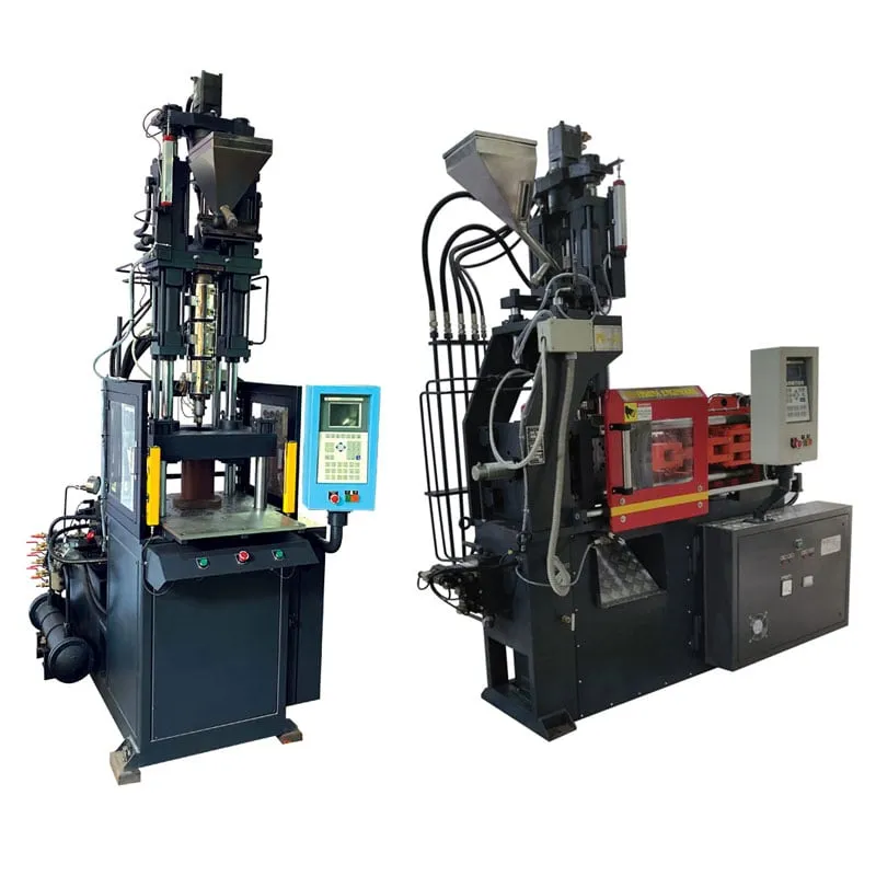

Double station vertical moulding machine working cycle at a glance
| Step | Under the clamp (centre) | At the open station |
|---|---|---|
| 1 | Lower half A slides in under the upper half | Lower half B moves out to its loading side |
| 2 | Clamp closes vertically and locks | Operator removes moulded parts from half B |
| 3 | Screw injects downward, then holds pressure | Operator loads new inserts into half B |
| 4 | Part cools in the closed mould | Inserts checked for seating; guard cleared |
| 5 | Clamp opens; parts stay in half A | Half B waits, loaded and ready |
| 6 | Table slides: half A out, half B in | Cycle repeats from the other side |
A double station vertical moulding machine working cycle runs two lower mould halves on a sliding table under one upper half. While one lower half is clamped and injected, the operator unloads and reloads the other at its side station. The table then slides and swaps the halves, so loading time hides inside moulding time.
The clamp moves vertically and the injection unit sits vertically above it, so inserts rest in the lower half under gravity. That combination is why the layout is common for insert and overmoulded parts.
Key Takeaways
- Two lower halves share one upper half, so loading at the side station overlaps with injection, hold and cooling under the clamp.
- The cycle is set by whichever is longer, clamp-closed time or loading time, plus the time the table takes to move between stations.
- Gravity holds inserts in the lower half, but every insert still needs a positive check that it is seated before the clamp closes.
- Both lower halves must match closely in shut height and alignment, because the same upper half closes on each of them in turn.
What is the double station vertical moulding machine working sequence, step by step?
The sequence alternates between two lower halves. Half A slides under the clamp, the clamp closes and locks, the vertical screw injects and holds, and the part cools. Meanwhile half B is unloaded and reloaded at its side station. The clamp opens, the table slides, and the roles swap.
Closing usually runs fast through most of the stroke and slows near the mould, so the platen does not strike a misplaced insert at full speed. Light curtains or interlocked guards at each side station keep hands out of the sliding zone while the table moves. Low-pressure mould protection over the last part of the stroke is the setting that saves inserts and cavities when something is out of place.
Injection comes from above, through the upper half. The nozzle meets a sprue in the upper half, and the melt flows down into cavities in the lower half. Because the screw sits over the clamp, the machine is tall but its footprint stays small.
When the clamp opens, the parts normally stay in the lower half so that the slide carries them out to the operator. Ejection at the side station, or lifting by hand for small insert parts, then frees the cavities for the next set of inserts.
What happens at the loading station while the other half moulds?
The operator, or a robot, removes the finished parts, clears any flash or runner, loads new inserts and confirms they are seated. All of that must finish within the clamp-closed time of the other half, or the machine waits and the second station adds little.
Moulding metal in has known risks: inserts can float or damage the mould, flash can enter internal threads, and slow loading stretches the cycle. Rounded inserts, knurling without sharp corners and an undercut for pull-out resistance help the part, while preheating inserts reduces post-mould shrinkage around them. Preheated inserts also reduce the cold spots that weaken the weld line around the metal.
Cracking from hoop stress around an insert is the most common complaint with moulded-in metal, and it can appear days later. A rough estimate of that stress is mould shrinkage multiplied by flexural modulus, and a boss of about 1.5 times the insert diameter is a common starting guide.
Automated cells add a check before the clamp closes. In one published cell, a robot loaded inserts from a vibratory bowl feeder and a vision camera confirmed that the cavities were clear and every insert was seated before moulding began.
Which parts and moulds suit a sliding double station machine?
Insert and overmoulded parts with loading times close to their moulding times suit it best. Typical examples are brass-insert electrical parts, terminals, cable ends and small assemblies with pins. Parts that need no inserts and eject cleanly usually run faster on a conventional single-station machine.
The tooling is usually one upper half and two matching lower halves, and that choice drives mould cost. Both lower halves must have the same shut height and must locate on the upper half with the same accuracy, or one station will flash while the other runs clean. Rotary tables follow the same logic, with more lower halves on a turning plate.
Indian electrical accessories show why this matters. Under the Electrical Accessories (Quality Control) Order, 2023, bayonet lamp holders to IS 1258:2005 and switch-socket-outlets to IS 15787:2008 need the Standard Mark, so a misplaced insert or poorly seated contact becomes a certification problem, not only scrap.
A flat view: treat the two lower halves as one tool with two faces. Maintain, measure and repair them together, because a station that drifts out of match will flash before anyone sees a dimension change.
What should you check before you trial a double station machine?
Time your insert loading by hand with a stopwatch, measure the shut height of both lower halves, and note the clamp-closed time from your current process. Bring those three figures to the trial so the station timing can be confirmed on the machine. See the vertical injection moulding machine page.
Frequently Asked Questions About Double Station Vertical Machines
Why does a double station machine use a vertical clamp?
A vertical clamp lets the lower mould half face upward, so inserts sit in their pockets under gravity while the operator works. A sliding table can then carry the lower half in and out from under the clamp. A horizontal clamp would need magnets, pins or springs to hold every insert in place.
Does the upper mould half move with the table?
No. The upper half stays mounted on the moving platen above the moulding position, and only the lower halves travel. Each lower half meets the same upper half in turn, which is why the two lower halves must match closely in shut height, alignment and cavity detail.
What happens if an insert is not seated when the clamp closes?
At best, low-pressure mould protection stops the platen and an alarm sounds. At worst, the insert is crushed, the cavity is damaged and a part leaves with an exposed or tilted insert. That is why automated cells verify insert seating, often by vision, before the clamp closes.
Is a rotary table better than a sliding table?
It depends on the part and the floor. A sliding table moves two lower halves side to side and keeps the machine compact. A rotary table can carry two or more lower halves and rotate them, which suits more stations or a robot at one fixed position. Both overlap loading with moulding.
How do I know whether my process is limited by loading or by moulding?
Time both. Measure clamp-closed time from injection start to clamp open, then time a full unload, clean and reload at the station. Whichever is longer sets the cycle, plus the table move. If loading is longer, better fixtures or more hands help more than a faster machine.
Related Articles
- PV Series Plastic Injection Molding Machine Guide
- PHM Series Two Platen Injection Molding Machine: An Overview
- Vertical Locking Vertical Injection Sliding Double Station Machines
- Vertical Locking Horizontal Injection Moulding Machine: Maximizing Efficiency
Sources & References
- aPriori: Cost Model Guide: Insert Injection Molding Options
- PlasticsToday (IMM), summarising A. Miller: Design and material advice from the pros, Part 3: Insert molding essentials (Sept 2005)
- Robotic Industries Association via Smart Molding, J. Clark: Automated injection molding operation
- Gazette of India (DPIIT): Electrical Accessories (Quality Control) Order, 2023, S.O. 43(E)
Technical Disclaimer
Disclaimer: The information provided in this document is for general informational and educational purposes only. It is based on technical references and industry information available at the time of preparation and may be subject to change. It does not constitute engineering, technical, commercial or professional advice, nor does it constitute a quotation, specification, warranty or contractual commitment by Pratishna Engineers.
Actual injection moulding machine and process requirements vary according to the component design, material, mould, production volume, machine configuration and operating conditions. The information, examples, calculations and recommendations provided should be independently evaluated and verified for the specific application before making any equipment, process or production decision. Information obtained from third-party sources remains subject to the accuracy and limitations of those sources.
Limitation of Liability: Pratishna Engineers makes no representation or warranty, express or implied, regarding the completeness, accuracy or suitability of the information for any particular application. To the extent permitted by applicable law, Pratishna Engineers shall not be liable for any loss, damage, cost or consequence arising from reliance on or use of the information contained in this document. Final machine selection, configuration and application suitability should be confirmed with Pratishna Engineers based on complete and accurate project requirements.

