






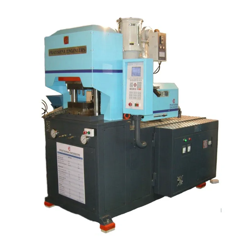

A vertical clamp horizontal injection machine closes the mould vertically and injects from the side, along the parting line. Use this checklist to see whether your part suits one.
1. Inserts, pins or cable ends must sit loose in the lower half and stay put by gravity.
2. A cable or wire runs across the mould and needs to exit at the parting line.
3. The part is an overmould on a metal or pre-moulded component.
4. A gate on the parting line suits the part better than a gate on the top face.
The more boxes you tick, the stronger the case for a trial on this layout.
Key Takeaways
- Vertical clamping lets inserts and cables rest in the lower half under gravity, while side injection keeps the top of the mould free for loading.
- Parting-line injection suits cable overmoulding, plug tops and parts where a gate mark on the top face is not acceptable or practical.
- Metal inserts bring hoop stress: plastic shrinks onto the insert, and a quick estimate of that stress is mould shrinkage multiplied by flexural modulus.
- Size clamp on the projected area at the parting plane, runner included, and add a reserve you choose rather than buying the largest frame.
Where does a vertical clamp horizontal injection machine fit best?
It fits parts that need something placed in the lower mould half before every shot, such as cables, pins, bushes or pre-moulded bodies, and that can be gated at the parting line. The horizontal injection unit stays clear of the loading area above the mould.
Cable overmoulding is the classic case. A power cord with a plug top, a sensor lead or a wire harness grommet lies across the lower half, the clamp closes over it, and melt enters from the side through a gate on the parting line. The cable never has to pass through the injection path.
Part types that suit vertical clamping with side injection
| Part | Why the layout suits it | Watch point |
|---|---|---|
| Cable plug top | Cord lies across the lower half; gate on the parting line | Clamping the cord without crushing the insulation |
| Sensor lead or grommet | Lead exits at the parting line | Sealing around the cable to stop flash |
| Connector with metal contacts | Contacts held on pins in the lower half | Contact position after injection |
| Handle on a metal shank | Shank stands in the lower half by gravity | Hoop stress around the shank |
| Overmould on a pre-moulded part | First part sits in a nest without extra fixtures | Bond between the two materials |
Plug tops show why accuracy matters. In India, IS 1293 covers plugs and socket-outlets, with tests for shock protection, resistance to abnormal heat and fire, and mechanical strength, plus 10,000 insertions and withdrawals in normal operation. A pin that shifts during overmoulding can fail those dimensional and safety checks.
Other good fits include connector bodies around metal contacts, handles moulded onto tool shanks and small housings overmoulded on a pre-moulded rigid part. Parts with no inserts that need a centre sprue gate usually run better on a standard horizontal machine, where they can drop clear.
How do inserts and overmoulding change part and mould design?
Inserts change three things: how they are held, how plastic grips them, and how much stress the shrinking plastic puts on them. Plan the insert seat, the knurl or undercut and the wall around the insert before you choose a machine, because the mould decides most of the result.
Moulding metal in is often treated as a last resort, because inserts can float, damage the mould or let flash into internal threads, and slow loading stretches the cycle. Many inserts can instead be pressed, snap-fitted or ultrasonically inserted after moulding. Mould them in when the joint carries high load or frequent disassembly.
Hoop stress causes the most common complaint, delayed cracking. Estimate it as mould shrinkage times flexural modulus. Acetal shrinks about 0.025 mm/mm against 0.016 for nylon, and one worked figure puts acetal hoop stress near 52.4 MPa, about 75% of its tensile strength. Toughened grades and preheated inserts lower the risk.
For geometry, round the insert and its knurling, avoid sharp corners and add an undercut for pull-out resistance. Let the insert protrude at least 0.4 mm into the cavity, keep at least one sixth of its diameter in plastic beneath it, and make the boss about 1.5 times the insert diameter.
What should you check on the machine itself?
Check the lower platen height and access, the injection unit alignment with the parting line, the table or shuttle option, and the clamp force at the parting plane. These four decide loading speed, gate consistency and whether the machine suits your mould without costly changes.
Loading height matters more than it looks. The operator reaches into the lower half every cycle, so a table at a comfortable working height and clear access from the front cut loading time and mistakes. Ask to stand at the machine during a trial and load your own inserts.
The nozzle must meet the parting line squarely. Side injection puts the sprue in the split, so any height mismatch between nozzle and parting plane shows up as flash at the gate or a damaged sprue bush. Confirm the nozzle height range against your mould before the order.
A shuttle table with two lower halves and one upper half lets the operator load one half while the other moulds. It helps when loading is slow, but output belongs in a separate calculation. Our flat view: get the fixed-table cycle stable with good inserts first, then add a shuttle.
What should you send for a machine recommendation?
Send the part drawing, the insert or cable details, the resin grade, the number of cavities and your target output. Note how the insert is located and where you can accept a gate mark. With that, the clamp, table and injection position can be matched to the job. See the vertical injection moulding machine page.
Frequently Asked Questions About Vertical Clamp, Side Injection Machines
What is the difference between vertical and horizontal injection on a vertical clamp machine?
Vertical injection enters through the top half, usually at the centre of the mould, while horizontal injection enters from the side along the parting line. Side entry keeps the top face free of a sprue and lets cables cross the mould, but it limits gate positions to the split.
Can I mould cable plug tops on a vertical clamp horizontal injection machine?
Yes, this is a typical use. The cord and pins sit in the lower half, the clamp closes, and melt enters at the parting line. Design the cable clamping so it seals against flash without crushing the insulation, and check pin positions after moulding on every new mould.
Should inserts be preheated before overmoulding?
Often, yes. Preheating reduces the temperature gap between metal and melt, which cuts post-mould shrinkage onto the insert, pre-expands it and improves weld lines around it. It matters most with large brass or steel inserts and with stiff, high-shrinkage resins such as acetal. Test with temperature cycling before approving the part.
How do I stop inserts from moving when the melt hits them?
Locate each insert on a pin or in a pocket with a close fit, and let the melt meet it from a direction that pushes it into its seat rather than off it. Magnets or spring clips can help with steel inserts. Check the first shots of every run for insert position.
Is overmoulding the same as two-shot moulding?
No. Overmoulding here means placing a finished component, such as a cable, metal part or pre-moulded body, into the mould and moulding over it in a separate cycle. Two-shot moulding makes both layers in one machine cycle with two injection units. The vertical clamp layout suits the first, loaded by hand or robot.
Related Articles
- Hybrid Injection Moulding Machines: Bridging Efficiency and Precision
- Vertical Locking Vertical Injection Sliding Double Station Machines
- Vertical Locking Horizontal Injection Moulding Machine: Maximizing Efficiency
- Vertical Injection Moulding Machine for Inserts
Sources & References
- PlasticsToday (IMM), summarising A. Miller, DuPont: Design and material advice from the pros, Part 3: Insert molding essentials
- BIS Blog, N. Agarwal: Standards for Plugs-Socket-Outlets and Switches
- Plastics Technology, J. Williams (RJG): Clamp Tonnage: More Is Better...Right?
- PlasticsToday: Shuttle table increases production
Technical Disclaimer
Disclaimer: The information provided in this document is for general informational and educational purposes only. It is based on technical references and industry information available at the time of preparation and may be subject to change. It does not constitute engineering, technical, commercial or professional advice, nor does it constitute a quotation, specification, warranty or contractual commitment by Pratishna Engineers.
Actual injection moulding machine and process requirements vary according to the component design, material, mould, production volume, machine configuration and operating conditions. The information, examples, calculations and recommendations provided should be independently evaluated and verified for the specific application before making any equipment, process or production decision. Information obtained from third-party sources remains subject to the accuracy and limitations of those sources.
Limitation of Liability: Pratishna Engineers makes no representation or warranty, express or implied, regarding the completeness, accuracy or suitability of the information for any particular application. To the extent permitted by applicable law, Pratishna Engineers shall not be liable for any loss, damage, cost or consequence arising from reliance on or use of the information contained in this document. Final machine selection, configuration and application suitability should be confirmed with Pratishna Engineers based on complete and accurate project requirements.

