






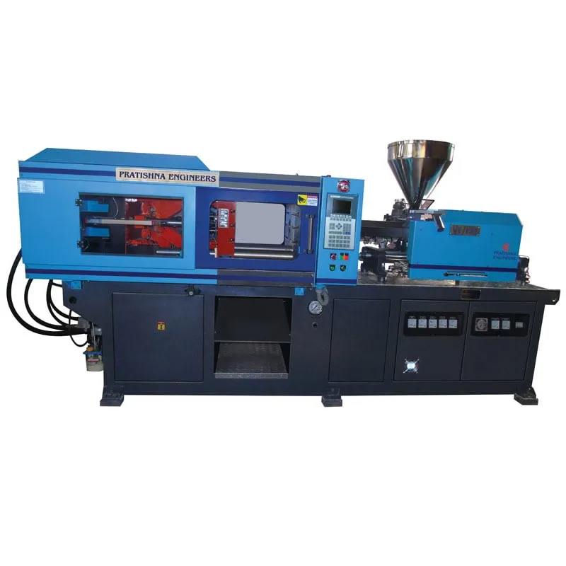

Your operator stands at a vertical-clamp machine, placing four brass inserts in the lower mould half while the clamp sits open and the barrel waits. The shot takes seconds; the loading takes longer than the cooling. That gap is where vertical locking horizontal injection output is won or lost. The clamp moves up and down while the injection unit lies flat and fires into the parting line, so inserts rest in the lower half by gravity. Add a shuttle table with two lower halves and one half is loaded while the other is moulded. How much that adds depends on two timings you can measure with a stopwatch.
Key Takeaways
- Output per hour equals 3,600 divided by the cycle in seconds, times cavities, times the share of good shots, so every second saved counts.
- A shuttle table hides loading time inside moulding time, but only until loading becomes longer than the closed-mould part of the cycle.
- Time the closed-mould period and the loading period separately before you buy a table, a second lower mould half or a robot.
- Horizontal injection into the parting line keeps the top of the mould free, which suits parts with several inserts loaded by hand.
What sets vertical locking horizontal injection output on the shop floor?
Three timings set it: the closed-mould time for injection, hold and cooling; the open-mould time for removing parts and loading inserts; and the table movement, if you have one. Output per hour is 3,600 divided by the total cycle, times cavities, times the good-shot share.
Cooling usually dominates the closed period. Cooling time rises with the square of wall thickness, and in one published trial on a 3.3 mm ABS part about 85% of the cycle was cooling. So the closed time is set mostly by the part design, not by the operator.
The open period is the opposite. It is almost all hand work: lifting parts out, clearing the cavity, placing inserts and checking that each one sits fully home. On a fixed lower half the machine does nothing during this time, and the barrel holds melt that is waiting.
The good-shot share matters more on insert jobs than on plain moulding. A missing or tilted insert can be crushed on closing, cause flash or leave a scrap part with a metal piece inside it. That is why insert cells often add a sensor or a camera to confirm inserts before the clamp closes.
How much does a shuttle table add?
A shuttle table lets the operator load one lower half while the other is being moulded, so the cycle becomes the longer of moulding or loading, plus the table move. When loading is close to the moulding time, output can rise by half or more over a fixed table.
A conventional shuttle uses one upper half and two lower halves. The catch is tooling: you pay for an extra lower half, and both halves must match closely enough that parts from either station pass the same inspection. Treat the two halves as two cavities to qualify, not one.
The table move is not free. Every slide adds dead time, and a single-slide arrangement that moves out and back on every cycle can end up slower than a fixed table. A double-station layout that alternates sides pays the move only once per cycle.
Fixed lower half vs shuttle table, 2 cavities, 22 s closed time, 2.5 s table move, 98% good shots (illustrative)
| Loading time (s) | Fixed: cycle and parts/h | Shuttle: cycle and parts/h | Gain |
|---|---|---|---|
| 10 | 32 s, 221 | 24.5 s, 288 | +31% |
| 16 | 38 s, 186 | 24.5 s, 288 | +55% |
| 22 | 44 s, 160 | 24.5 s, 288 | +80% |
| 28 | 50 s, 141 | 30.5 s, 231 | +64% |
The table shows the pattern. The gain peaks when loading equals the closed time, because the shuttle hides all of it. Below that, there is less loading to hide. Above it, the operator sets the pace and the mould waits.
When does the operator, not the mould, limit output?
The operator limits output once loading takes longer than the closed-mould time. From that point a shuttle table cannot help further, because the mould waits for the hands. Cutting loading time, through better insert presentation, fewer inserts or a robot, is then the only lever.
Watch where the seconds go. Operators often spend more time picking inserts from a loose tray than placing them. A nest that presents inserts in the mould pattern pays back quickly: if placement drops from 2 s to 1.5 s per insert on a ten-insert part, the open time falls by 5 s.
Robots give consistent open times, and consistent open times keep mould temperature steady, which helps dimensions. In one published cell, a robot unloaded a four-cavity mould, loaded inserts from a vibratory feeder and used vision to confirm the inserts were seated before each shot.
If your inserted parts are switch components, check the end-product rules too. Switches to IS 3854 are under compulsory BIS certification, so a tilted insert that slips past the press still fails at the brand owner. Put plainly, buying a shuttle table for a job where loading already exceeds the closed time solves the wrong problem.
What should you measure before changing your cell?
Time ten cycles on the current job and split each one into closed time, loading time and any table move. Note the good-shot share over a full shift. With those four numbers you can work out what a table, a fixture or a robot would add. See the vertical injection moulding machine range for clamp and table options.
Frequently Asked Questions About Vertical Clamp, Horizontal Injection Output
Is a vertical clamp with horizontal injection the same as a fully vertical machine?
No. On a fully vertical machine the injection unit sits above the mould and injects down through the top half. With horizontal injection the unit lies flat and injects into the parting line. That keeps the top of the mould free for loading and changes how the runner must be designed.
Can I add a shuttle table to an existing vertical-clamp machine?
Sometimes. It depends on whether the frame, the lower platen and the controls were designed for a table, and on free space at both sides. You also need a second lower mould half that matches the first. Ask the machine builder to confirm table load, travel and guarding before you commit.
How do I count good shots on an insert moulding job?
Count every part the machine produces over a full shift and every part that passes inspection, then divide good parts by total parts. Include parts scrapped for missing, tilted or loose inserts, flash and short shots. Track insert faults separately, because they point to loading rather than to the process.
Does a rotary table give more output than a shuttle table?
Not by itself. Both tables let loading overlap moulding, so output still follows the longer of the two times plus the index move. A rotary table helps when you need a third station, for robot unloading or an inspection camera, so that loading and unloading are split between people or machines.
Why does insert preheating matter for output?
Cold metal inserts chill the melt around them, which can weaken weld lines and raise stress in the plastic around the insert. Preheating reduces that stress and post-moulding shrinkage. The output link is scrap: parts that crack later around the insert count against your good-shot share, even if they looked fine at the press.
Related Articles
- Hybrid Injection Moulding Machine: Revolutionizing Production
- Horizontal Injection Moulding Machine
- Vertical Locking Horizontal Injection Moulding Machine: A Synergy of Design and Efficiency
- Vertical Locking Vertical Injection Sliding Double Station Machines
Sources & References
- PlasticsToday: Shuttle table increases production (Aug 2008)
- RJG Inc.: How to Determine Injection Molding Cooling Time (Mar 2021)
- Robotic Industries Association via Smart Molding, J. Clark: Automated injection molding operation
- Bureau of Indian Standards: Scheme I (ISI Mark Scheme) products under compulsory certification
Technical Disclaimer
Disclaimer: The information provided in this document is for general informational and educational purposes only. It is based on technical references and industry information available at the time of preparation and may be subject to change. It does not constitute engineering, technical, commercial or professional advice, nor does it constitute a quotation, specification, warranty or contractual commitment by Pratishna Engineers.
Actual injection moulding machine and process requirements vary according to the component design, material, mould, production volume, machine configuration and operating conditions. The information, examples, calculations and recommendations provided should be independently evaluated and verified for the specific application before making any equipment, process or production decision. Information obtained from third-party sources remains subject to the accuracy and limitations of those sources.
Limitation of Liability: Pratishna Engineers makes no representation or warranty, express or implied, regarding the completeness, accuracy or suitability of the information for any particular application. To the extent permitted by applicable law, Pratishna Engineers shall not be liable for any loss, damage, cost or consequence arising from reliance on or use of the information contained in this document. Final machine selection, configuration and application suitability should be confirmed with Pratishna Engineers based on complete and accurate project requirements.

