






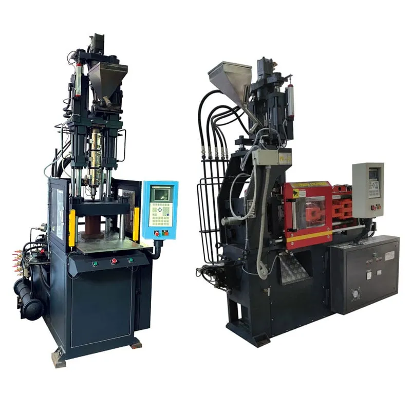

A sliding table double station moulding machine pays for itself when loading and unloading take a large share of the cycle. With one top mould half and two lower halves, the operator loads one station while the other moulds, so the cycle becomes the longer of moulding and loading, plus the table move. In a generic case with 30 s mould-closed time, 26 s of loading and a 3 s slide, cycle time drops from 56 s to 33 s, about 70% more parts per hour. When loading is short, the gain can fall below 10%.
Key Takeaways
- Cycle on a sliding double station equals the longer of mould-closed time and loading time, plus the table move, so the slower task sets the pace.
- The gain is largest when loading time is close to mould-closed time; with short loading, the table move eats most of the saving.
- A single sliding table with one lower half can be slower than a fixed table, because it adds two table moves without any overlap.
- Budget for a second lower mould half and identical cavities in both, because both halves must give the same part dimensions every shot.
When does a sliding table double station moulding machine pay for itself?
It pays when loading time is a large share of mould-closed time and the work is manual or slow to automate. Compare the fixed-table cycle, moulding plus loading, with the double station cycle, the longer of the two plus the table move. The ratio is your output gain.
Output gain at 30 s mould-closed time and a 3 s table move (calculated)
| Loading time | Fixed table cycle | Double station cycle | Output gain |
|---|---|---|---|
| 6 s | 36 s | 33 s | +9% |
| 12 s | 42 s | 33 s | +27% |
| 18 s | 48 s | 33 s | +45% |
| 26 s | 56 s | 33 s | +70% |
| 30 s | 60 s | 33 s | +82% |
| 40 s | 70 s | 43 s | +63% |
The table shows the pattern. Gain climbs as loading time approaches mould-closed time and peaks when the two are equal. Once loading runs longer than moulding, the mould waits for the operator and the gain starts to fall again, so the fix shifts to faster loading.
Real loading times can be long. In one published automation case, unloading a four-cavity insert mould, inspecting the cavities for debris, then loading and verifying the inserts took 30 s. That is the kind of job where a second station earns its keep.
Our flat view: if loading is under about a fifth of mould-closed time, keep the fixed table and spend on a better insert feeder or gripper. The second station only pays when there is real waiting to overlap. Check the gain against the cost of the second lower half before you order.
How does a sliding double station differ from fixed and rotary tables?
A fixed table keeps one lower half under the clamp, so loading happens while the mould is open and the machine waits. A sliding double station shuttles two lower halves sideways. A rotary table turns two or more lower halves around a centre and suits more stations.
A single sliding table is a different thing. It carries one lower half out for safe loading and back in for moulding, which helps access but adds two moves to every cycle. In the 30 s and 26 s example it gives 62 s, about 10% slower than the fixed table.
Conventional shuttle setups have one known drawback: the machine must wait for the first part to cool in the clamp before it can mould the second. The table hides loading behind moulding, but cooling stays inside the mould-closed time, so wall thickness still sets the floor of the cycle.
Rotary tables make sense when a part needs more than two steps outside the clamp, such as loading, inspection and unloading at separate stations. For a single operator handling one insert set at a time, the sliding double station is usually the simpler choice.
Floor space also changes. A sliding double station needs room on both sides of the clamp for the table travel and for safe access at each loading position, so check the layout drawing before you plan the aisle.
What does a second station demand from the mould and the shop floor?
It demands a second lower mould half that matches the first, a table that stops in the same place every time, and an operator routine that fits inside the moulding time. Without all three, the two stations give different parts or the press waits anyway.
Tooling is the main added cost. The usual set is two lower halves and one upper half, and that choice drives tooling cost in costing models. Both lower halves need matched cavities, cooling and insert seats, or every second part comes out different.
Some insert-moulded electrical parts fall under compulsory certification. Under the Electrical Accessories (Quality Control) Order, 2023, bayonet lamp holders to IS 1258:2005 and switch-socket-outlets to IS 15787:2008 need the Standard Mark, so keep cavity identification on both lower halves for traceability.
Plan the operator routine on a stopwatch. Unload, blow out debris, place inserts, check seating and press the cycle start, all inside the mould-closed time of the other station. If the routine overruns, add a fixture, a vision check or a feeder before you add a second operator.
Safety needs the same attention. The operator works beside a moving table at every cycle, so guarding, a clear stop position and interlocks on the loading side belong in the order, not in a later retrofit.
What figures should you collect before deciding?
Time your current cycle in two parts: mould-closed time and the open time spent unloading and loading. Note cavities, good-part share and the shifts you run. Those figures show the output gain directly and tell you whether a feeder, a fixture or a second station is the better next step. See the vertical injection moulding machine range.
Frequently Asked Questions About Sliding Double Station Machines
Does a sliding double station machine need two operators?
Usually not. The point of the second station is that one operator loads one lower half while the other is moulding, so the operator works during the time the machine would otherwise wait. A second operator only helps when the loading routine is longer than mould-closed time and cannot be shortened.
How long does the table move take?
It depends on table size, mould weight and the drive, so take the figure from the machine trial rather than a brochure. In the examples on this page a 3 s move is an assumption. Every second of table move is added to each cycle, so a slow table eats into the gain quickly.
Can a robot replace the second station?
Sometimes. A robot with an insert feeder can cut loading time enough that a fixed table loses little time, as in published cells that load inserts from a bowl feeder and verify them by vision. If the robot still needs longer than a few seconds, a double station plus robot gives more output.
Do both lower mould halves need their own cooling circuits?
Yes. Each lower half needs its own cooling connection that stays connected as the table slides, or quick couplings that reconnect reliably. Match flow and temperature on both, because a warmer half gives different shrinkage and dimensions. Log part weights by station for the first runs to confirm the two halves agree.
Which parts suit a sliding double station best?
Parts with slow manual loading suit it best: multiple inserts, cable ends, metal contacts or fragile pre-moulded bodies that must be seated by hand. Parts that drop free with no inserts gain little, because their open time is short. Jobs where loading time is close to mould-closed time give the largest gain.
Related Articles
- Vertical Locking Horizontal Injection Moulding Machine: A Synergy of Design and Efficiency
- Hybrid Injection Moulding Machines: Bridging Efficiency and Precision
- Vertical Locking Vertical Injection Sliding Double Station Explained
- Vertical Locking Horizontal Injection Moulding Machine: Maximizing Efficiency
Sources & References
- PlasticsToday: Shuttle table increases production
- aPriori Cost Model Guide: Insert Injection Molding Options
- Robotic Industries Association via Smart Molding, J. Clark: Automated injection molding operation
- Gazette of India (DPIIT): Electrical Accessories (Quality Control) Order, 2023
Technical Disclaimer
Disclaimer: The information provided in this document is for general informational and educational purposes only. It is based on technical references and industry information available at the time of preparation and may be subject to change. It does not constitute engineering, technical, commercial or professional advice, nor does it constitute a quotation, specification, warranty or contractual commitment by Pratishna Engineers.
Actual injection moulding machine and process requirements vary according to the component design, material, mould, production volume, machine configuration and operating conditions. The information, examples, calculations and recommendations provided should be independently evaluated and verified for the specific application before making any equipment, process or production decision. Information obtained from third-party sources remains subject to the accuracy and limitations of those sources.
Limitation of Liability: Pratishna Engineers makes no representation or warranty, express or implied, regarding the completeness, accuracy or suitability of the information for any particular application. To the extent permitted by applicable law, Pratishna Engineers shall not be liable for any loss, damage, cost or consequence arising from reliance on or use of the information contained in this document. Final machine selection, configuration and application suitability should be confirmed with Pratishna Engineers based on complete and accurate project requirements.

